Network system of transmission equipment and remote upgrading method of network system

A technology for transmission equipment and network systems, applied in transmission systems, electromagnetic wave transmission systems, electrical components, etc., can solve problems such as spending a lot of time on maintenance and updating, high packet loss rate in remote upgrades, and low data transmission throughput. Understand and maintain, improve the transfer rate, improve the effect of data throughput

Active Publication Date: 2016-11-23
WUHAN HONGXIN TELECOMM TECH CO LTD
View PDF5 Cites 7 Cited by
  • Summary
  • Abstract
  • Description
  • Claims
  • Application Information

AI Technical Summary

Problems solved by technology

[0003] The HDLC link of the traditional digital optical fiber repeater equipment has the disadvantages of low data transmission throughput and slow data transmission speed, so the traditional remote upgrade solution upgrades relatively slowly and takes a lot of time
Because the traditional remote upgrade requires packet transmission, the remote upgrade of the device has a high packet loss rate and poor stability.
Proprietary software data transmission protocol for HDLC links, which takes a lot of time and effort to maintain and update, and has poor versatility

Method used


Image

  • Network system of transmission equipment and remote upgrading method of network system
  • Network system of transmission equipment and remote upgrading method of network system
  • Network system of transmission equipment and remote upgrading method of network system

Examples


Embodiment 1

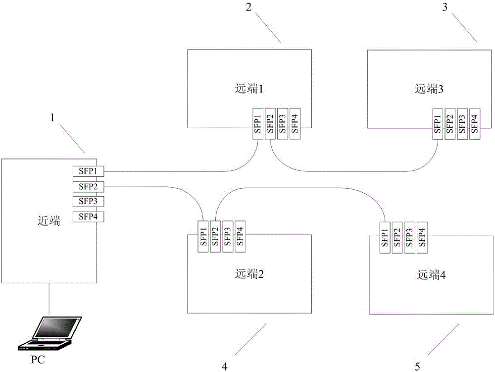
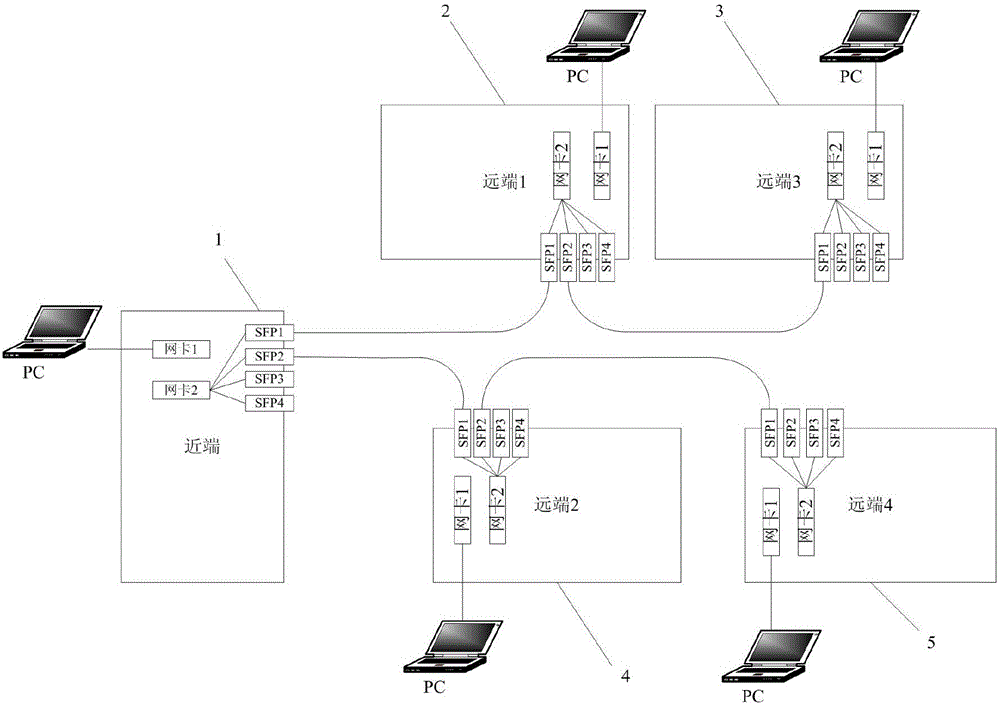
[0034] Take the star network as an example, such as figure 2 shown in figure 1 A network system of transmission equipment is proposed on the basis of , including a PC terminal, a near-end equipment, and four remote equipment. Both the near-end device and the far-end device include four digital laser modules (SFP optical modules for short), network card 1, and network card 2.

[0035] The network IP address of the PC is set to the same network segment as the IP1 address of the near-end device, which is mainly used for external communication; the IP2 address of the near-end device is not in the same network segment as the IP1 address, and is mainly used for internal data communication transmission of the system. Among them, the network port corresponding to network card 1 is mainly connected to the PC terminal, and the PC terminal controls the transmission equipment through the dedicated upper computer software to perform stand-alone testing; the network card 2 corresponds to ...

Embodiment 2

[0050] This embodiment 2 is a method embodiment, which belongs to the same technical concept as the above-mentioned system embodiment 1. Please refer to the system embodiment for the content not described in detail in the method embodiment.

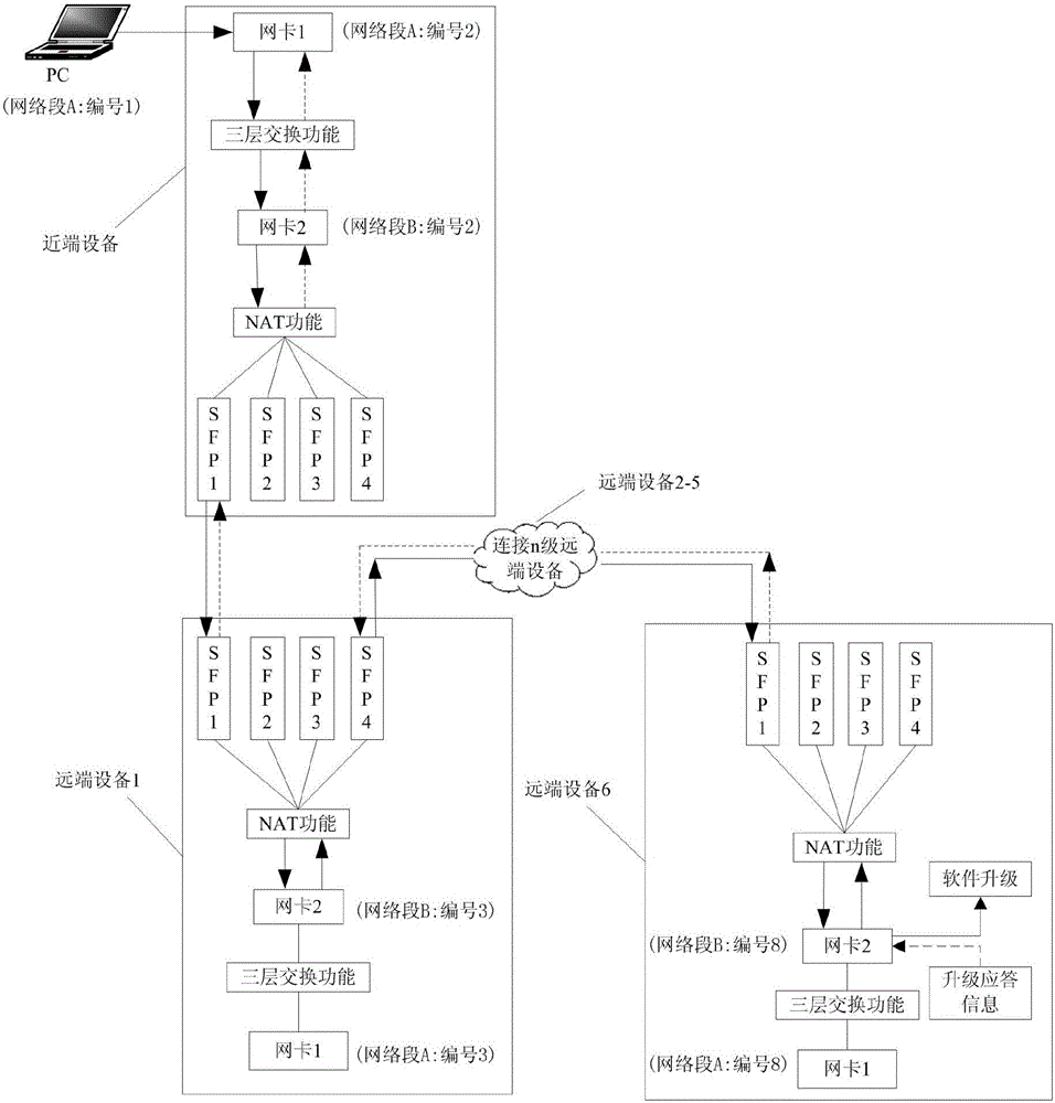
[0051] In a network transmission system of transmission equipment, the novel remote upgrade method proposed by the present invention uses image 3 The remote device 6 in the networking mode is an example of a device that needs to be remotely upgraded, and its specific implementation process is as follows:

[0052] Step 1), according to image 3 Complete the networking of the transmission equipment, and run the upper computer software of the transmission equipment on the PC side. The remote upgrade function of the remote device 6 can be realized on the near-end device through the host computer software.

[0053] Step 2), first correctly configure the following information on the host computer software: the network IP address of the devic...


PUM


Abstract

The invention provides a network system of transmission equipment and a remote upgrading method of the network system. Near-end equipment and far-end equipment are each provided with two network cards and two network IP addresses, two network IP segments are available for networking of the whole transmission equipment system, one network segment address is selected and used for external communication, and the other network segment is used for internal network transmission of the equipment system. The three-layer forwarding technology and the NAT (network address translation) technology are adopted for completing the routing function between the network cards, and network data communication of different network segments between the network cards is achieved. In this way, data transmission between the equipment is completed through an IP data packet, and the remote upgrading function is achieved through an FTP (file transfer protocol). The throughout of data transmitted between the equipment is large, the transmission speed is high, and stability is good. The equipment upgrading function supports breakpoint resume, a complete user permission management system is provided, and safety is high. Auxiliary supporting technical documentation is mature, and maintainability is high.

Description

technical field [0001] The invention relates to the field of optical fiber communication and wireless communication, in particular to a network system of transmission equipment and a remote upgrading method thereof. Background technique [0002] In the currently known digital optical fiber repeater equipment, monitoring data transmission is performed between the equipment through HDLC (high-level data link control) links. The device remote upgrade function is realized based on HDLC link transmission data. The near-end device loads the upgrade package file into the near-end system through the proprietary host computer software, then decomposes the upgrade file into several packages, and sends a single package of data to the remote system through the HDLC link. After several transmissions, the remote The end device receives the complete upgrade data package, and the remote device starts to update the software. [0003] The HDLC link of the traditional digital optical fiber r...

Claims


Application Information

Patent Timeline
Patent Type & Authority Applications(China)
IPC IPC(8): H04B10/077H04L29/06H04L29/08H04L29/12
CPCH04B10/0773H04L61/2521H04L63/0428H04L63/10H04L67/025H04L67/06H04L69/22
Inventor 赵舟伟饶志恒熊磊刘永飘
Owner WUHAN HONGXIN TELECOMM TECH CO LTD
Why Eureka
Try Eureka