System and method of measuring and correcting tilt angle of lens

A technology of lens and measurement unit, which is applied in the direction of measuring device, lens position determination, TV system components, etc., can solve the problem of lens resolution impact, and achieve the effect of improving productivity and accuracy

Inactive Publication Date: 2016-11-23
SAMSUNG ELECTRO MECHANICS CO LTD
View PDF8 Cites 18 Cited by
  • Summary
  • Abstract
  • Description
  • Claims
  • Application Information

AI Technical Summary

Problems solved by technology

[0009] Meanwhile, in the case where the optical axis of the lens is not set perpendicular to the imaging surface of the image sensor but inclined at a certain angle relative to the imaging surface due to various factors generated during the assembly process of the camera module, the resolution of the lens rate has a negative impact on

Method used


Image

  • System and method of measuring and correcting tilt angle of lens
  • System and method of measuring and correcting tilt angle of lens
  • System and method of measuring and correcting tilt angle of lens

Examples


Embodiment Construction

[0029] Exemplary embodiments of the present disclosure will now be described in detail with reference to the accompanying drawings.

[0030] However, this disclosure may be embodied in many different forms and should not be construed as limited to the embodiments set forth herein. Rather, these embodiments are provided so that this disclosure will be thorough and complete, and will fully convey the scope of the disclosure to those skilled in the art.

[0031] In the drawings, the shapes and dimensions of elements may be exaggerated for clarity, and the same reference numerals will be used throughout to designate the same or like parts.

[0032] First the terminology with respect to direction will be defined. The optical axis direction refers to the vertical direction based on the lens 10 .

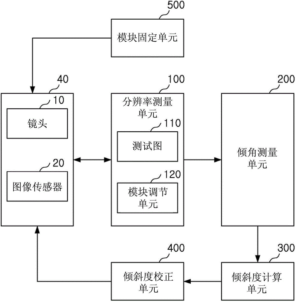
[0033] figure 1 is a block diagram of a system for measuring and correcting a tilt angle of a lens according to an exemplary embodiment of the present disclosure.

[0034] refer to fi...


PUM


Abstract

A system and a method of measuring and correcting an angle of tilt of a lens are provided. A resolution of the lens is measured using a test chart, and it is selected whether or not a tilt of the lens is corrected depending on whether or not the measured resolution of the lens is equal to or greater than a preset value. Whereby, productivity of a camera module may be improved.

Description

[0001] This application claims priority and benefits from Korean Patent Application No. 10-2014-0116480 filed with the Korean Intellectual Property Office on September 2, 2014, the disclosure of which is hereby incorporated by reference. technical field [0002] The present disclosure relates to a system and method for measuring and correcting the tilt angle of a lens. Background technique [0003] Recently, a digital camera function has been included in most mobile communication terminals. With improvements in functions of digital cameras included in mobile communication terminals, camera modules including high pixel image sensors have been commonly used. [0004] Such a camera module has an auto focus function for automatically focusing (AF) a subject, wherein the auto focus function is performed by controlling an actuator such as a voice coil motor (VCM). [0005] In such an autofocus operation, the lens can be moved from the macro focus position to the infinity focus po...

Claims


Application Information

Patent Timeline
Patent Type & Authority Applications(China)
IPC IPC(8): H04N17/00
CPCG02B7/023G02B7/365H04N17/002G01M11/0214G01M11/0221G01M11/0264G01B11/26H04N23/55G02B7/36
Inventor 金玄波丹诺夫·伊里亚李敬勋
Owner SAMSUNG ELECTRO MECHANICS CO LTD
Why Eureka
Try Eureka