Press-moulded article manufacturing method and vehicle lower arm
一种制造方法、成型品的技术,应用在装在枢轴上的悬臂、车辆部件、运输和包装等方向
- Summary
- Abstract
- Description
- Claims
- Application Information
AI Technical Summary
Problems solved by technology
Method used
Image

Examples
no. 1 Embodiment approach
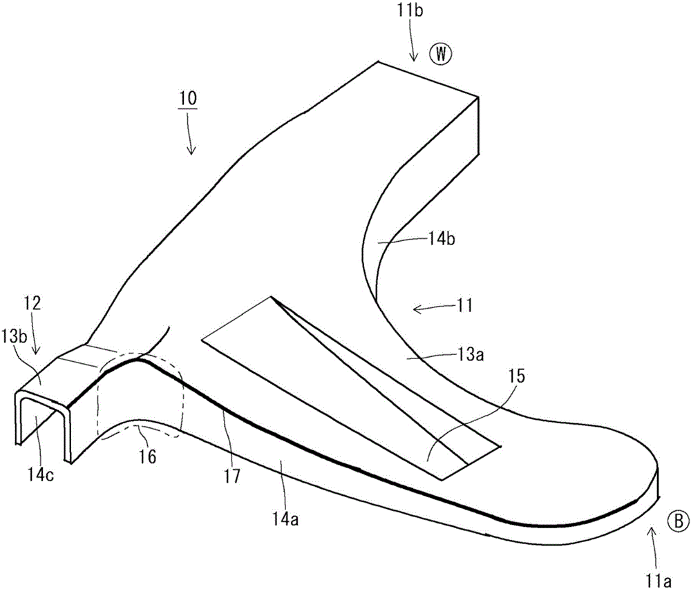
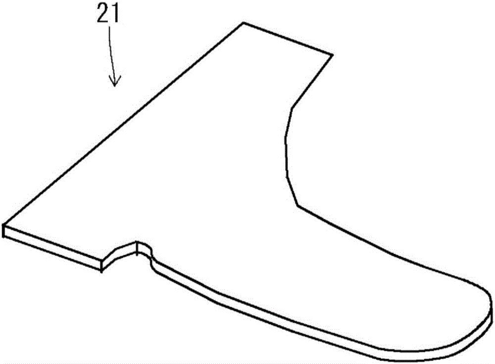
[0097] Figure 9A ~ Figure 9C It is a perspective view explaining an example of the manufacturing process of the manufacturing method of 1st Embodiment about the press-formed product formed as a lower arm. in these pictures Figure 9A Indicates the shape of the raw metal plate. Figure 9B Shows the shape of the metal plate after the first step. Figure 9C Shows the shape of the press-formed product obtained through the second step. The manufacturing method of the first embodiment is to manufacture figure 1 The case of the press-formed product 10 of the first example shown is the object. Such as figure 1 and Figure 9C As shown, the groove portion 15 of the press-formed product 10 is provided only in the area of the surface of the top plate portion 13a of the main body portion 11 closer to the first end portion (end portion for vehicle body attachment) 11a than the base of the protrusion portion 12 . Additionally, in order to get Figure 9C The press-formed product 10...
no. 2 Embodiment approach
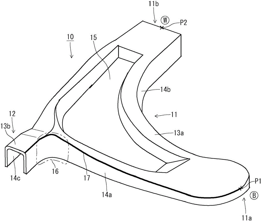
[0115] Figure 11A ~ Figure 11C It is a perspective view explaining an example of the manufacturing process of the manufacturing method of 2nd Embodiment about the press-formed product formed as a lower arm. in these pictures Figure 11A Indicates the shape of the raw metal plate. Figure 11B Shows the shape of the metal plate after the first step. Figure 11C Shows the shape of the press-formed product obtained through the second step. Figure 12 It is a perspective view which schematically shows the shape example of the mold used in the 1st process of the manufacturing method of 2nd Embodiment. The manufacturing method of the second embodiment is to manufacture figure 2 The case of the press-formed product 10 of the second example shown is the object. Such as figure 2 and Figure 11C As shown, the groove portion 15 of the press-formed product 10 is provided on the surface of the top plate portion 13a of the main body portion 11 from the first end portion (the end po...
Embodiment 1
[0147] In the test of Example 1, in order to confirm the effect of the first embodiment, the figure 1 A press-formed product having the shape of the first example shown. In this press-formed product, the groove portion is provided only in the region of the surface of the top plate portion of the main body portion on the side of the first end portion. At this time, the raw material metal plate was a high-tensile steel plate having a plate thickness of 2.6 mm and a tensile strength of 980 MPa class.
[0148] In Example 1 of the present invention, using the Figure 10 and Figure 6 die shown, using the Figure 9A and Figure 9B shown in the 1st process as well as the Figure 9B and Figure 9C In the second step shown, press work is performed on the raw material metal plate.
[0149] On the other hand, in Conventional Example 1, using the Figure 5 and Figure 6 die shown, using the Figure 3A and Figure 3B shown in the 1st process as well as the Figure 3B and Figu...
PUM
 Abstract
Description
Claims
Application Information
 - R&D
- Intellectual Property
- Life Sciences
- Materials
- Tech Scout
- Unparalleled Data Quality
- Higher Quality Content
- 60% Fewer Hallucinations
Browse by: Latest US Patents, China's latest patents, Technical Efficacy Thesaurus, Application Domain, Technology Topic, Popular Technical Reports.
© 2025 PatSnap. All rights reserved.Legal|Privacy policy|Modern Slavery Act Transparency Statement|Sitemap|About US| Contact US: help@patsnap.com