Ventilation system for supercharged combustion engines

A technology of a ventilation system and a supercharger, applied in the field of ventilation system, can solve the problems of increasing the pressure difference between the separated oil and the crankcase, and the deterioration of the separated oil return, and achieve the effect of high oil separation rate

Inactive Publication Date: 2016-11-23
REINZ DICHTUNGS
View PDF7 Cites 6 Cited by
  • Summary
  • Abstract
  • Description
  • Claims
  • Application Information

AI Technical Summary

Problems solved by technology

This, in turn, involves the following disadvantage: the pressure control takes place only in relation to the crankcase pressure and the differential pressure at the oil-air separator
For most cases, although the switching arrangement of the oil-air separator and pressure control valve may increase the pressure differential available for oil-air separation, at the same time it will increase the pressure differential between the separated oil and the crankcase pressure, and thus the separated oil The reflux is even exacerbated by

Method used


Image

  • Ventilation system for supercharged combustion engines
  • Ventilation system for supercharged combustion engines
  • Ventilation system for supercharged combustion engines

Examples


Embodiment Construction

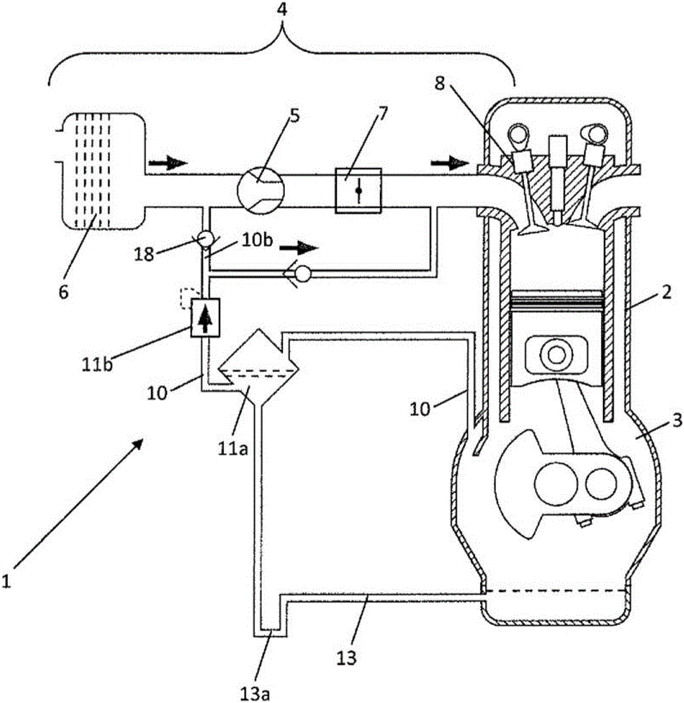
[0042] As already described above, figure 1 An internal combustion engine according to the prior art is shown.

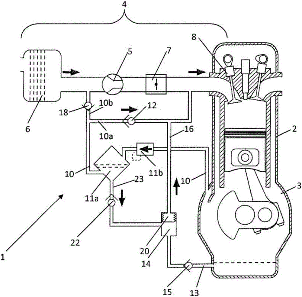
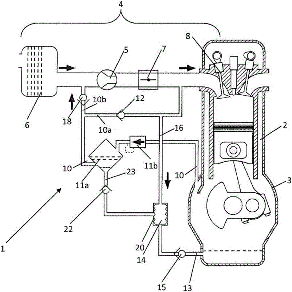
[0043] figure 2 A further internal combustion engine 2 is shown, which has been adapted according to the invention. For this purpose, a bellows is arranged in the tank 14 as the actuating element 20 . The line 23 to the tank 14 also includes a check valve 22 as tank inlet valve, which closes at excess pressure compared to the pressure in the portion 10 e of the vent line 10 . Here, the ventilation line 10 comprises a portion 10a to a portion 10e. Furthermore, in the return line 13 from the tank 14 to the crankcase 3 (via which the separated oil flows back into the crankcase 3 ), a check valve 15 is provided as a tank outlet valve, which check valve 15 closes at a higher pressure in the crankcase relative to the pressure in tank 14 .

[0044] Branching from this ventilation line 10 is a connecting line 16 which, in the present case, operates as a ventilation li...


PUM


Abstract

The present invention relates to a Ventilation system for a crankcase for the transport of blow-by gases from the crankcase to the intake section of an internal combustion engine with supercharger, with a ventilation line reaching from the crankcase to the segment of the intake section between the supercharger and the air inlet valve, an air-oil separator arranged in the ventilation line, as well as a return line for the return of oil separated in the air-oil separator via a tank and a tank outlet valve into the crankcase, characterized in that an actuating element is arranged in or at the tank, which actuating element is charged ventilation system for supercharged combustion engineswith the pressure in the intake line behind the supercharger as working pressure and which upon sufficiently high pressure transports the oil present in the tank via the tank outlet valve into the crankcase.

Description

technical field [0001] The invention relates to a ventilation system for a crankcase of an internal combustion engine. Background technique [0002] In the crankcase of an internal combustion engine, blow-by gases that occur for reasons of environmental protection are usually guided to the intake of the combustion engine. The pressure differential between the crankcase and the inlet is used in order to return blowby air from the crankcase into the inlet. [0003] Thus, a ventilation system for a crankcase for transporting blow-by gases usually comprises a ventilation line which goes from the crankcase to the inlet. In addition, an oil separator is arranged in the ventilation line to separate oil and oil mist contained in the blow-by gases from these blow-by gases. The oil separator and / or return line may include a tank for the separated oil. The separated oil then flows back from the oil separator to the crankcase. It should be emphasized that, in the context of the pres...

Claims


Application Information

Patent Timeline
Patent Type & Authority Applications(China)
IPC IPC(8): F01M13/04F02M25/06
CPCF02M25/06F01M13/04F01M13/0011F01M13/022F01M2013/0044F01M2013/027F01M2013/0494Y02T10/12F01M13/00F01M13/02F01M13/023
Inventor 凯-乌韦·莱姆克罗伯特·巴赖特尔
Owner REINZ DICHTUNGS
Why Eureka
Try Eureka