
Machine tool

A technology of machine tools and robots, applied in the directions of manipulators, metal processing machinery parts, maintenance and safety accessories, etc., can solve problems such as the inability to achieve cooling, and achieve the effect of preventing machine tool failures or reducing operating efficiency

Inactive Publication Date: 2016-11-30
FANUC LTD
View PDF3 Cites 4 Cited by
  • Summary
  • Abstract
  • Description
  • Claims
  • Application Information

AI Technical Summary

Problems solved by technology

In addition, in recent years, the number of machine tools using water-soluble cutting fluid has increased, and the possibility of the misty cutting fluid adhering to parts far from the processing point has increased.
For example, when foreign matter adheres to the blades of the fan or the flow path of the cooling fluid is blocked by foreign matter, sometimes the desired cooling effect cannot be achieved
In the past, in order to clean various cooling components used in machine tools, it was necessary to remove the fan cover or the housing of the motor to clean the inside, which took a lot of labor in the cleaning process.

Method used


Image

  • Machine tool
  • Machine tool
  • Machine tool

Examples


Embodiment Construction

[0027] Hereinafter, embodiments of the present invention will be described with reference to the drawings. In order to facilitate the understanding of the present invention, the dimensions of the constituent elements of the illustrated embodiments are appropriately changed. In addition, the same reference numerals are used for the same constituent elements or corresponding constituent elements.

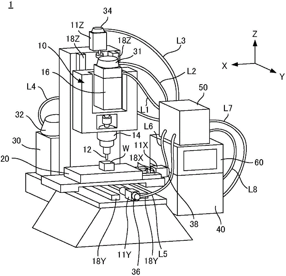
[0028] figure 1 It is a perspective view showing the machine tool 1 of one embodiment. The machine tool 1 includes: a spindle device 10; a table 20 for placing a workpiece W; an amplifier 40 for supplying electric power to the driving parts of the spindle device 10 and the table 20; a cleaning fluid supply device 50 for supply of cleaning fluid; and a control device 60 for controlling the amplifier 40 and the cleaning fluid supply device 50 .

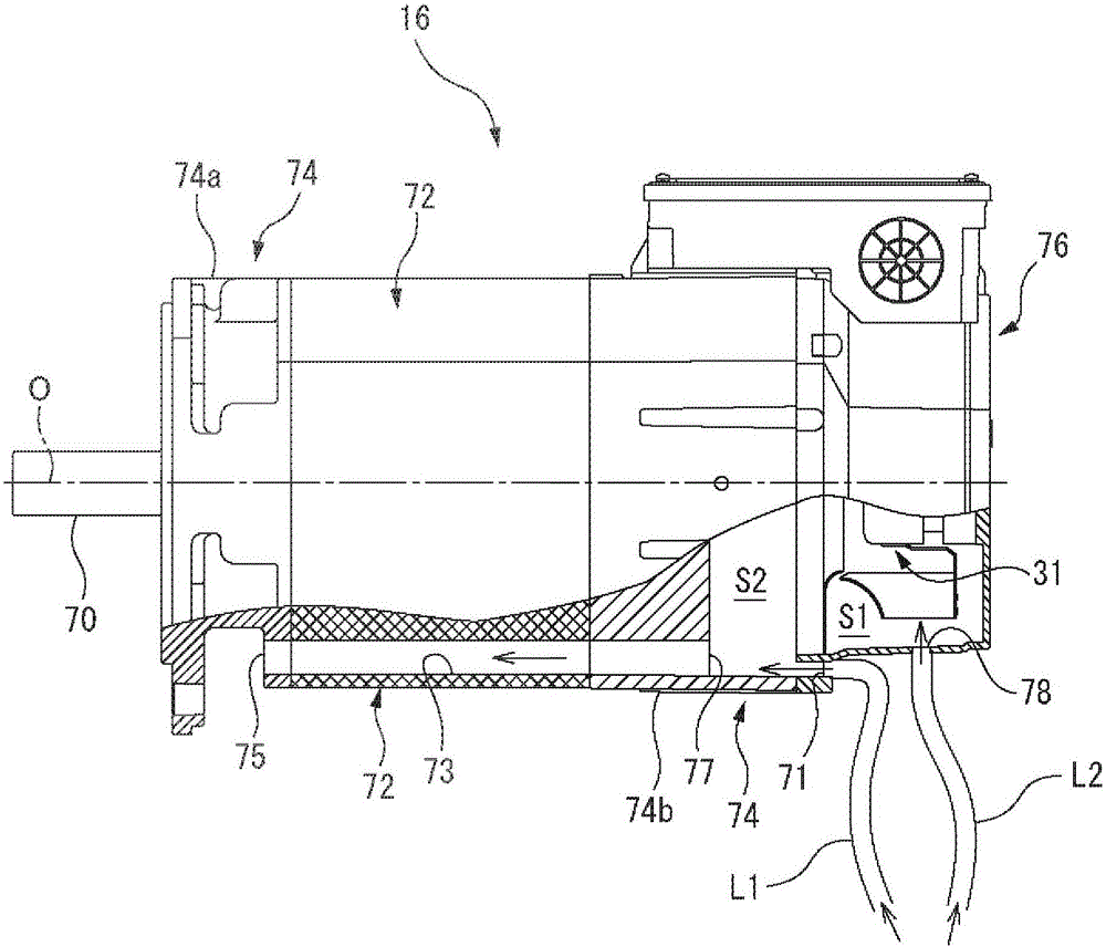
[0029] The spindle device 10 includes: a spindle 14 on which a tool 12 is provided; and a spindle motor 16 for rotating the spindle 14 arou...


PUM


Abstract

A machine tool is disclosed in the invention and includes a cooling fluid supplying part, e.g., a fan or a flow path, for supplying a cooling fluid which dissipates heat generated from the machine tool during operation. The cooling fluid supplying part is operable to supply the cooling fluid independently of a cooling action of a machining point of the machine tool. The machine tool also includes a cleaning part for cleaning the cooling fluid supplying part. The cooling fluid supplying part may be a fan or a flow path of the cooling fluid. Accordingly, the cooling effect for cooling the machine tool can be prevented from being decreased due to the foreign objects attached to the cooling fluid supplying part; the machine tool can be prevented from being damaged due to excessive heat, and the operation efficiency can be prevented from being decreased.

Description

technical field [0001] The invention relates to a machine tool with cleaning elements. Background technique [0002] Among machine tools, there is known a machine tool having a cleaning member for cleaning chips and the like adhering to a spindle or a workpiece during machining. In addition, there is known a machine tool configured to execute a cleaning program stored in a control device. [0003] Japanese Patent Application Laid-Open No. 11-033874 discloses a machine tool capable of switching supply of cutting fluid supplied from an axis for cooling a tool and air used for cleaning a tool holder. [0004] Japanese Unexamined Patent Publication No. 60-186154 discloses a machine tool configured to be able to automatically replace a cleaning tool and a cutting tool and to clean a workpiece while moving a spindle. [0005] Japanese Patent Application Laid-Open No. 2008-155324 discloses a machine tool configured to automatically find an appropriate cleaning path and to set con...

Claims


Application Information

Patent Timeline
Patent Type & Authority Applications(China)
IPC IPC(8): B23Q11/10B23Q11/00
CPCB23Q11/00B23Q11/10B23Q11/005B25J19/021B25J11/0085
Inventor 中泽康之
Owner FANUC LTD
Learn More