Self-locking material clamping device with buffer

A buffer and material technology, applied in chucks, manufacturing tools, manipulators, etc., can solve problems such as emptying, potential safety hazards, material falling off, etc., and achieve the effect of compact overall structure, reduced overall weight, and guaranteed stability.

Active Publication Date: 2016-11-30
SUZHOU XINYOUHUA INVESTMENT ADVISOR CO LTD
View PDF9 Cites 32 Cited by
  • Summary
  • Abstract
  • Description
  • Claims
  • Application Information

AI Technical Summary

Problems solved by technology

Pneumatic actuators are relatively simple in structure, low in energy consumption, and fast in response, but their positioning accuracy and reliability are not as good as those of electric actuators
Moreover, the pneumatic actuators that work for a long time, the pneumatic components are easy to age, and gas leakage often occurs. At this time, the pneumatic actuator is prone to falling off due to insufficient clamping force when grasping materials.
In addition, in extreme conditions such as high temperature and severe cold, the environmental adaptability of pneumatic actuators is worse
[0004] According to the design of the robot end effector in the past, whether it is an electric actuator or a pneumatic actuator, usually only the realization of the material gripping action is considered in the design process, and the end effector actually grabs the material when it contacts with the material. The impact and accurate positioning of the actuator are rarely considered, so it is difficult to guarantee the reliability, stability and safety of the actuator in the working process.
It often happens that the material is damaged due to the impact of the end effector, the material falls off due to unreliable clamping, and there are adverse situations such as emptying and missing clamping.
For example, the publication date is September 21, 2011, and the invention application with the publication number CN102189542A discloses a semiconductor wafer transport manipulator, which can handle the center alignment problem of wafers with different diameters, but its structure and positioning methods are relatively Complicated, it is difficult to realize the control of the actuator
In addition, the rigid contact force generated at the moment of contact between the manipulator and the material has not been considered, so there are certain safety hazards when the manipulator grips the material

Method used


Image

  • Self-locking material clamping device with buffer
  • Self-locking material clamping device with buffer
  • Self-locking material clamping device with buffer

Examples


Embodiment Construction

[0038] The specific implementation manners of the present invention will be further described in detail below in conjunction with the accompanying drawings and embodiments. The following examples are used to illustrate the present invention, but are not intended to limit the scope of the present invention.

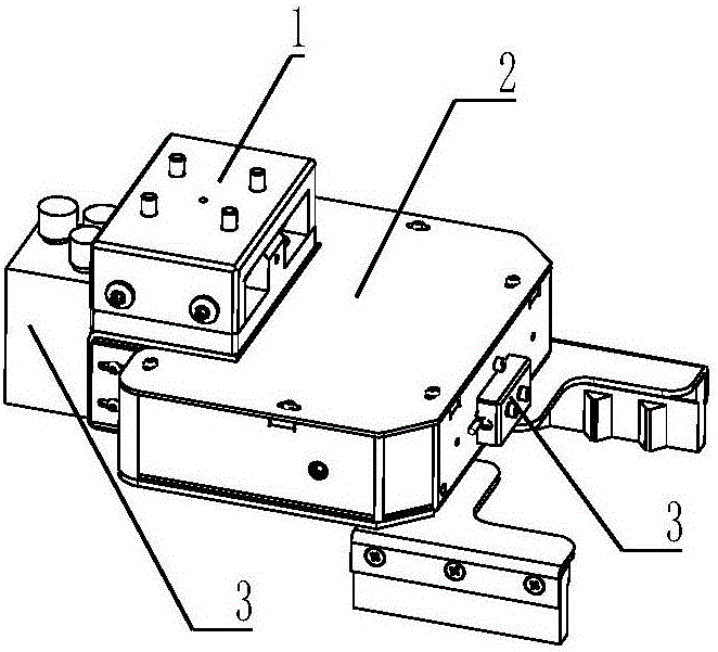
[0039] Such as figure 1 As shown, a self-locking material grasping device with a buffer according to the present invention includes a spring buffer mechanism 1 , an electric gripper 2 and a measuring element 3 .

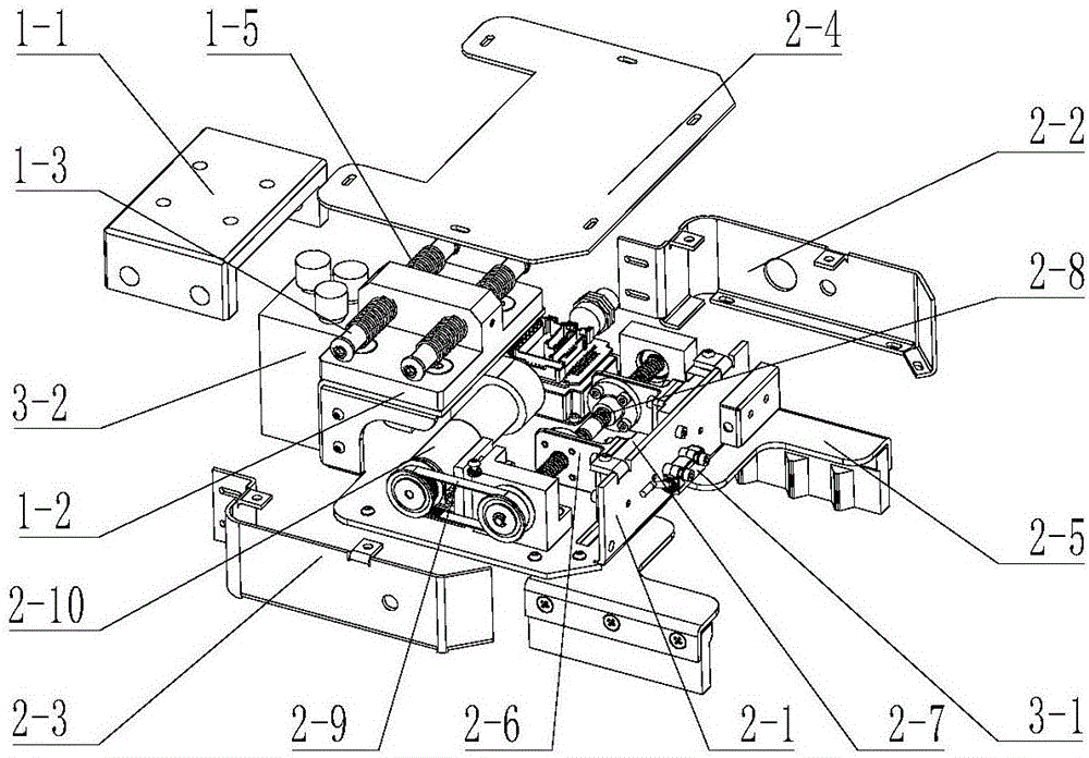
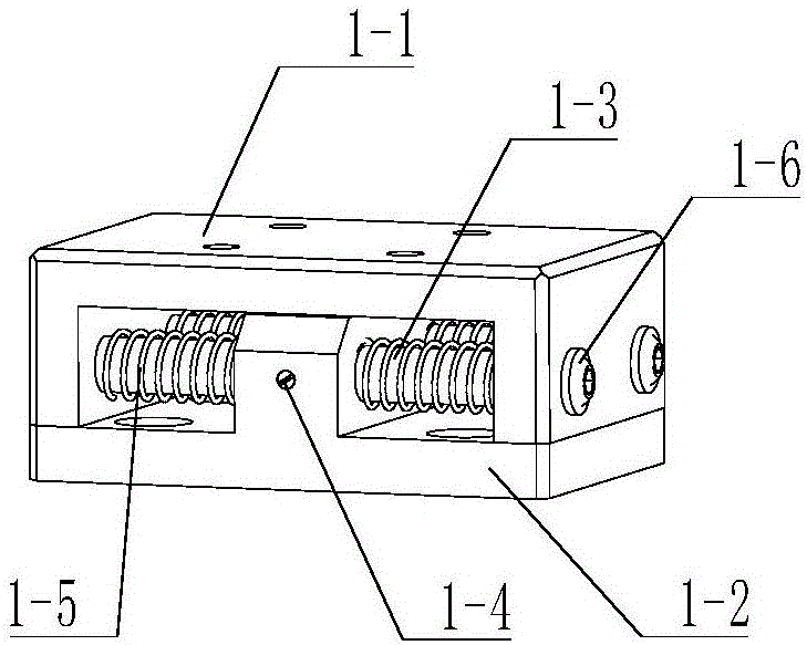
[0040] combine figure 1 , figure 2 , image 3 , Figure 4 with Figure 10 , the spring buffer mechanism 1 is composed of 1 connecting block 1-1, 1 first slide block 1-2, 2 guide shafts 1-3, 2 set screws 1-4, 4 springs 1-5 and 4 A group of connecting screws 1-6 is composed. The self-locking material gripping device 100 with a buffer is fixed on the mounting flange 20 at the end of the 6-DOF mechanical arm 10 through the connecting block 1-1, the first slid...


PUM


Abstract

The invention relates to a self-locking material clamping device with a buffer. The self-locking material clamping device comprises an electric clamping jaw, a spring buffer mechanism and a measurement element, the electric clamping jaw comprises a mounting plate, and two opposite grippers and a driving component driving the grippers to move face to face or back to back are arranged on the mounting plate; the spring buffer mechanism comprises a connecting block and a first slider in sliding connection with the connecting block and in connection with the mounting plate, two parallel guide shafts are connected to the connecting block, a perpendicular protrusion is arranged in the middle of the first slider, the protrusion sleeves the middles of the two guide shafts, and the guide shafts are sleeved with springs butting against the side wall of the connecting block and the side wall of the protrusion; the measurement element comprises a photoelectric sensor, a photoelectric switch and a visual sensor, the photoelectric sensor which is located between the two grippers is used for detecting whether materials are clamped by the electric clamping jaw or not, the electric clamping jaw is used for limiting when the grippers are closed and opened, and the visual sensor is used for identifying a positioning piece fixed to a material platform so as to acquire relative position information of the materials relative to the grippers.

Description

technical field [0001] The invention relates to a mechanical gripper, in particular to a self-locking material gripping device with a buffer. Background technique [0002] With the rapid development of mechatronics technology, traditional industries are gradually transforming into modern industrial automation models. Warehousing and logistics robots play an important role in today's automated factories and become a profitable tool for operators. They not only save labor and cost, but also greatly improved the operating efficiency of the factory. When the logistics robot is actually operating in an automated factory, the role of the end effector should not be underestimated. The combination of the flexible multi-degree-of-freedom operating manipulator and the exquisite end effector is a reliable guarantee for efficient material handling. [0003] At present, the two types of robot end effectors are mainly electric actuators and pneumatic actuators. Electric actuators usuall...

Claims


Application Information

Patent Timeline
Patent Type & Authority Applications(China)
IPC IPC(8): B25J15/00B25J15/02B25J19/02
CPCB25J15/00B25J15/02B25J19/02
Inventor 赵俊伟戴军王宏军林睿厉茂海
Owner SUZHOU XINYOUHUA INVESTMENT ADVISOR CO LTD
Why Eureka
Try Eureka