Coupled constraint compensation type transfer bridge for offshore personnel or cargo transshipment
A restraint compensation, cargo technology, applied in the direction of cargo handling equipment, transportation and packaging, ships, etc., can solve the problem that the roll and pitch motion of the ship cannot be compensated, so as to reduce the contact area, improve the feasibility, reduce the processing and assembly effect of difficulty
- Summary
- Abstract
- Description
- Claims
- Application Information
AI Technical Summary
Problems solved by technology
Method used
Image
Examples
Embodiment 1
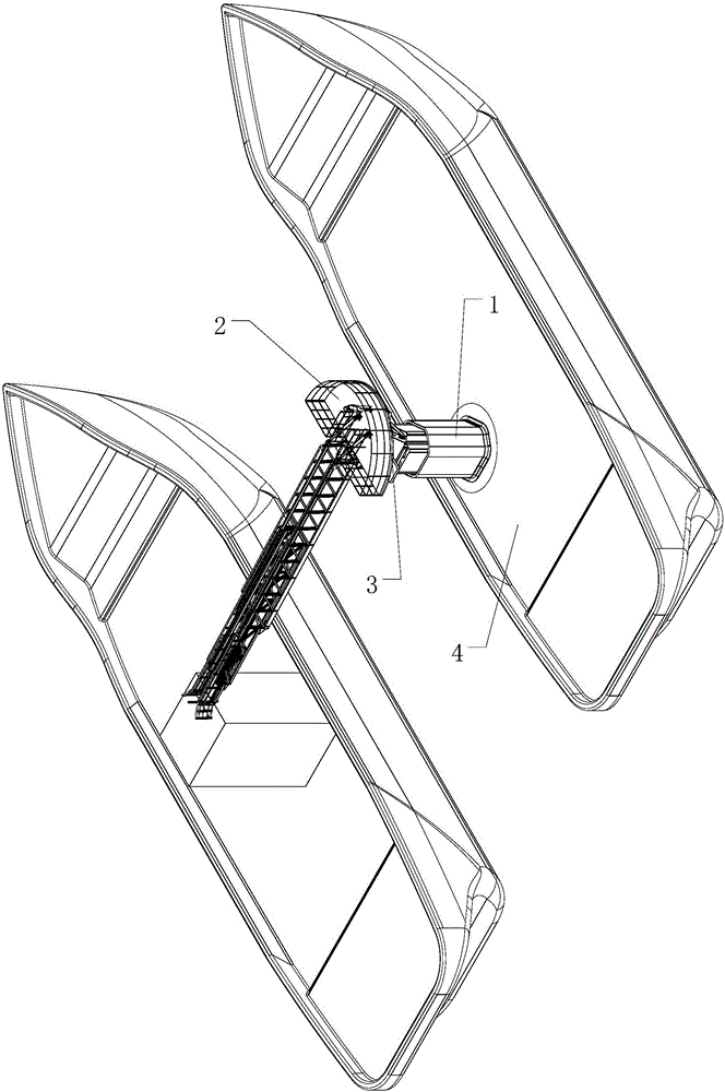
[0033] exist figure 1 In the schematic diagram of the coupling-constraint-compensated pick-up bridge for personnel or cargo transfer at sea, the bottom of the coupling-constraint three-degree-of-freedom parallel stable platform 1 is fixed on the deck 4 of the hull, and its upper end passes through the first rotating pair 3 and the four-freedom degree bridge arm 2 connection;
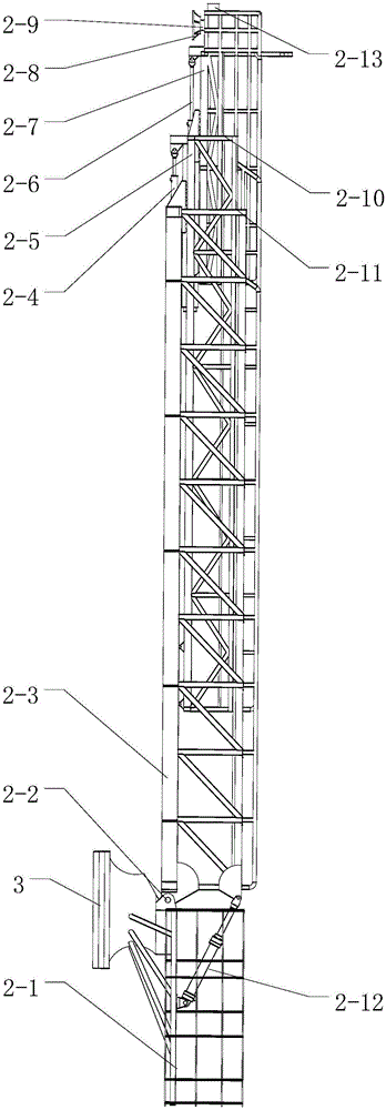
[0034] Such as figure 2 As shown, the bottom of one end of the first bridge arm 2-3 in the four-degree-of-freedom bridge arm is connected with the transfer platform 2-1 through two coaxial third rotating pairs 2-2, and the second linear drive unit 2-12 The two ends are respectively connected to the transfer platform and the upper part of the first bridge arm through ball joints; the second bridge arm 2-5 is connected to the first bridge arm through the third moving pair 2-11, and the third linear drive unit 2-4 One end of the cylinder barrel is fixedly connected to the bottom of the first bridge arm, ...
Embodiment 2
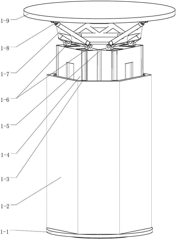
[0038] Such as Figure 8 As shown, the tops of the extension ends of the three long sliders 1-4 are respectively provided with the bases of three coaxial second rotating pairs 1-6 in groups of two, and the six first moving pairs are double guide rail slider guide rail pairs 1-12, the double guide rail slider guide rail pairs are parallel to each other and are all perpendicular to the plane of the mounting base 1-1, the three second moving pairs 1-12 are double guide rail slider guide rail pairs, and the double guide rail slider guide rail pairs are mutually Parallel and perpendicular to the plane of the disk of the mounting seat, the axis direction of the coaxial second rotating pair in groups of two by two is perpendicular to the moving direction of the first and second moving pairs, and the first and second rotating pairs in groups of two by three The axes of the two revolving pairs are arranged in a triangle.
[0039] Such as Figure 9 As shown, the first and second movin...
Embodiment 3
[0042] Such as Figure 10 As shown, the tops of the extension ends of the three long sliders 1-4 are respectively provided with the bases of three coaxial second rotating pairs 1-6 in groups of two, and the six first moving pairs are combined rolling guide rail pairs 1-13 are parallel to each other and are all perpendicular to the plane of the mounting base 1-1, and the three second moving pairs are double guide rail slider guide rail pairs 1-12, and the double guide rail slider guide rail pairs are parallel to each other and are all perpendicular to the mounting base 1 The plane of -1, the axis direction of the coaxial second rotating pair in groups of two by two is perpendicular to the moving direction of the first and second moving pairs, and the axes of three second rotating pairs in groups of two by two are arranged in a triangle .
[0043] Such as Figure 11 As shown, the first moving pair is a combined rolling guide rail pair 1-13; the combined rolling guide rail pair...
PUM
 Abstract
Description
Claims
Application Information
 - R&D
- Intellectual Property
- Life Sciences
- Materials
- Tech Scout
- Unparalleled Data Quality
- Higher Quality Content
- 60% Fewer Hallucinations
Browse by: Latest US Patents, China's latest patents, Technical Efficacy Thesaurus, Application Domain, Technology Topic, Popular Technical Reports.
© 2025 PatSnap. All rights reserved.Legal|Privacy policy|Modern Slavery Act Transparency Statement|Sitemap|About US| Contact US: help@patsnap.com


