Separation method and system for transverse wave propagation in crack

A separation method and separation system technology, applied in the field of separation of shear waves propagating in cracks, can solve the problems of low accuracy of shear waves propagating in cracks, and achieve high accuracy and simple analysis and calculation process

Active Publication Date: 2016-11-30
CHINA UNIV OF MINING & TECH (BEIJING)
View PDF5 Cites 0 Cited by
  • Summary
  • Abstract
  • Description
  • Claims
  • Application Information

AI Technical Summary

Problems solved by technology

[0003] The technical problem to be solved by the present invention is that the accuracy of the fast and slow wave separation method of crack propagating shear waves in the prior art is low

Method used


Image

  • Separation method and system for transverse wave propagation in crack
  • Separation method and system for transverse wave propagation in crack
  • Separation method and system for transverse wave propagation in crack

Examples


Embodiment 1

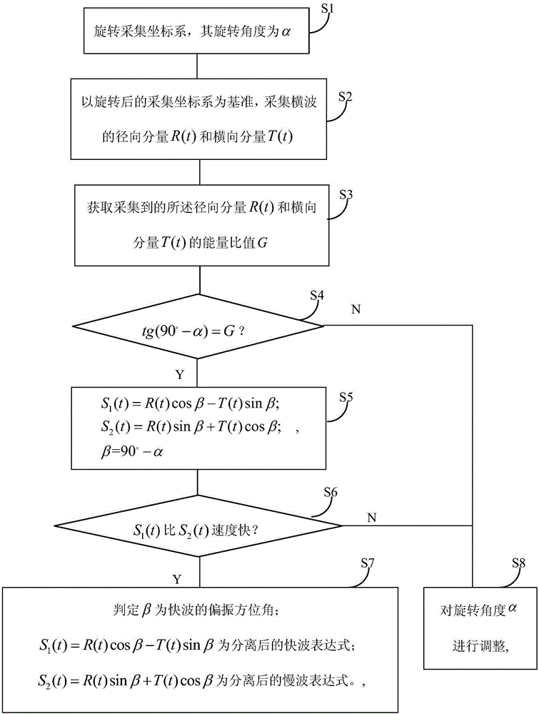
[0055] This embodiment provides a method for separating shear waves propagating in cracks, such as figure 1 shown, including the following steps:

[0056] S 1 : Rotate the acquisition coordinate system, the rotation angle is α, and the rotation angle is based on the counterclockwise direction. In this step, there is no specific requirement for the rotation direction of the acquisition coordinate system, but the final rotation angle is based on the counterclockwise direction. For example, it can be rotated 240° clockwise, and the final rotation angle is 120° counterclockwise. Then the rotation angle is 120°. As another measurement method, it can be considered that the clockwise rotation angle is negative and the counterclockwise rotation angle is positive. For example, if the clockwise rotation is 30°, it can be considered as -30° counterclockwise rotation.

[0057] S2: Based on the rotated collection coordinate system, collect the radial component R(t) and transverse compo...

Embodiment 2

[0091] This embodiment provides a shear wave separation system propagating in a crack, such as Figure 6 shown, including:

[0092] Rotation unit 1, which rotates the acquisition coordinate system, and its rotation angle is the angle α in the counterclockwise direction;

[0093] Acquisition unit 2, based on the rotated acquisition coordinate system, acquires the radial component R(t) and transverse component T(t) of the shear wave, where t is the propagation time of the shear wave in the crack;

[0094] A data acquisition unit 3, which acquires the energy ratio G of the collected radial component R(t) and transverse component T(t);

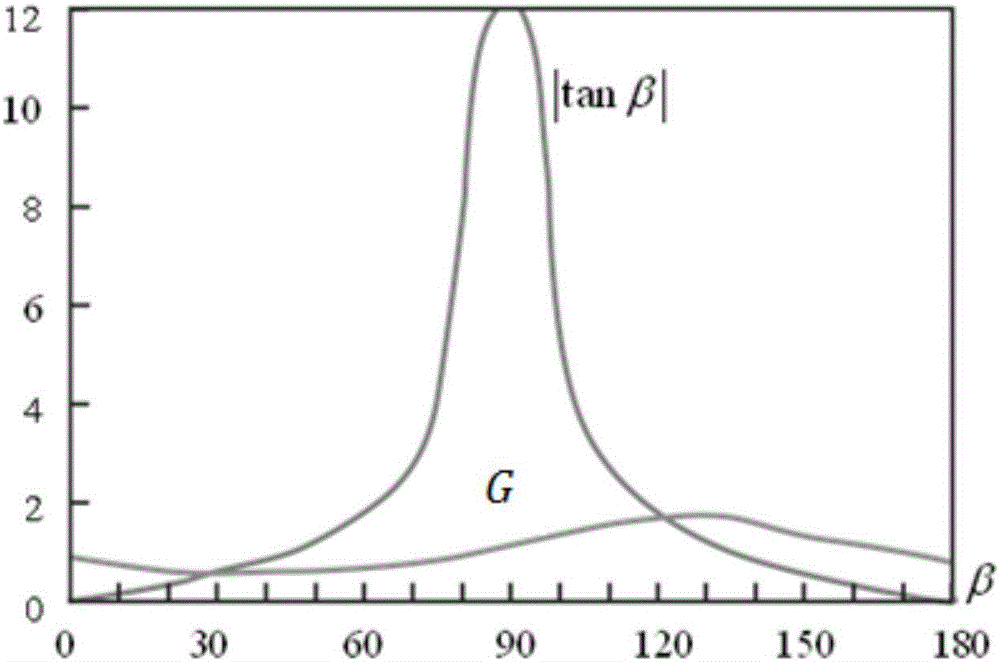
[0095] The first judging unit 4 judges whether the rotation angle α satisfies tg(90°-α)=R;

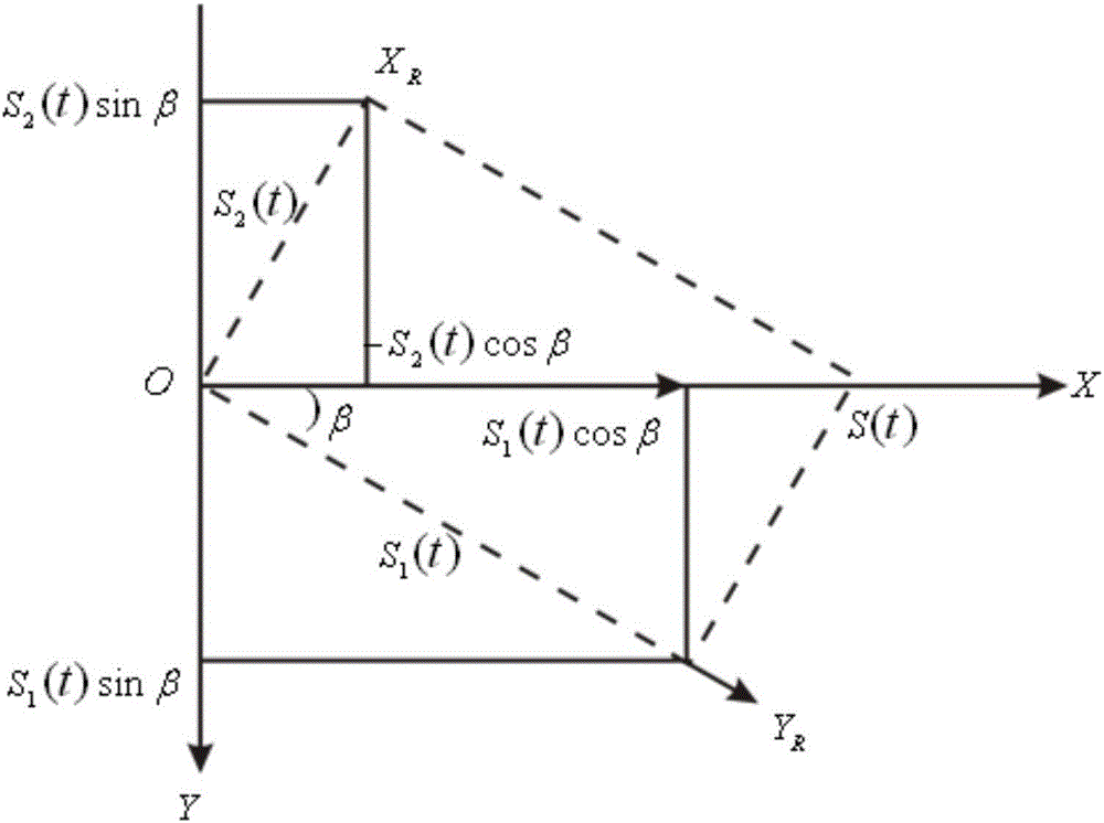
[0096] The processing unit 5, when the determination result of the determination unit 4 is yes, acquires the fast wave component S 1 (t) and the slow wave component S 2 Expression of (t): S 1 (t)=R(t)cosβ-T(t)sinβ; S 2 (t)=R(t) sinβ+T(t)cosβ; where, ...

Embodiment 3

[0104] This embodiment provides an identification mark for the orientation of coal seam fissures. In order to establish the change relationship between the coal seam conversion wave field and the coal seam fissures, a forward modeling simulation is performed on the coal seam fissure model. Coal seam geological model such as Figure 7 As shown, all the strata are horizontally layered, and the coal seam fractures are vertical fractures parallel to each other, and the direction is parallel to the Y axis. The parameters corresponding to each layer are shown in Table 1.

[0105] Table 1 Physical property parameters of coal seam geological model

[0106]

[0107] Excited at point O, received on a circular survey line with point O as the center and radius r (r=1400m in the model), the azimuth angle θ of the crack is calculated from the X axis (that is, the direction of true north), and the model is calculated using the reflectivity method The wave field of , the subwave is select...


PUM


Abstract

The present invention provides a separation method and system for transverse wave propagation in a crack. A collection coordinate system is rotated according to a setting angle, and if the rotation angle of the collection coordinate system is namely a fast wave polarization azimuth, the collection coordinate system is overlapped with a natural system of coordinates. If the rotation angle of the collection coordinate system is [Beta], the radial component R(t) after rotation is namely a slow wave component, and the transverse component T(t) is namely a fast wave component. Meanwhile, the energy ratio of the fast wave component and the slow wave component is an energy ratio of the radial component R(t) and the transverse component T(t) obtained through measurement, and the ratio should be equal to the tangent value of the crack direction azimuth. Through taking the relation mentioned above as a theoretical basis, it is analyzed whether the energy ratio of the radial component R(t) and the transverse component T(t) obtained through measurement after the collection coordinate system is rotated is equal to the tangent value of the rotation angle or not, and when the energy ratio of the radial component R(t) and the transverse component T(t) obtained through measurement after the collection coordinate system is rotated is equal to the tangent value of the rotation angle, the rotation angle is defined as the polarization azimuth of the fast wave. The separation method and system for transverse wave propagation in the crack are simple in the analysis operation process, fit into the current theory and have high accuracy.

Description

technical field [0001] The invention relates to the technical field of seismic exploration, in particular to a separation method and system for shear waves propagating in cracks. Background technique [0002] When a shear wave propagates in a cracked anisotropic medium, the polarization direction of the incident shear wave changes and splits into two independent shear waves whose polarization directions are perpendicular to each other. These two shear waves propagate with different amplitudes and velocities, among which the shear wave parallel to the fracture direction is faster, called the fast wave, which is represented by S 1 Indicates; the velocity of shear wave perpendicular to the direction of fracture is relatively slow, which is called slow wave, which is expressed by S 2 express. Such as figure 2 Shown by the fast wave S 1 and slow wave S 2 The direction-determined fracture azimuth coordinate system is called the natural coordinate system, and the coordinate sy...

Claims


Application Information

Patent Timeline
Patent Type & Authority Applications(China)
IPC IPC(8): G01V1/30
CPCG01V1/30G01V2210/646
Inventor 杜文凤彭苏萍李晓婷
Owner CHINA UNIV OF MINING & TECH (BEIJING)
Why Eureka
Try Eureka