Materials for thermoelectric energy conversion

A thermoelectric material, thermoelectric technology, applied in TEG. field, capable of solving problems such as damage to materials, generation of ineffective power, etc.

Inactive Publication Date: 2016-11-30
ROBERT BOSCH GMBH
View PDF2 Cites 5 Cited by
  • Summary
  • Abstract
  • Description
  • Claims
  • Application Information

AI Technical Summary

Problems solved by technology

Exposure to excessively high exhaust gas temperatures above this upper limit may damage these mater

Method used


Image

  • Materials for thermoelectric energy conversion
  • Materials for thermoelectric energy conversion
  • Materials for thermoelectric energy conversion

Examples


Embodiment Construction

[0022] For the purposes of promoting an understanding of the principles of the disclosure, reference will now be made to the embodiments illustrated in the accompanying drawings and described in the following written description. It is understood that no limitation of the scope of the present disclosure is thereby intended. It is further to be understood that this disclosure covers any adaptations and modifications to the illustrated embodiments and includes further applications of the principles of the disclosure as commonly occur to those skilled in the art to which this disclosure pertains.

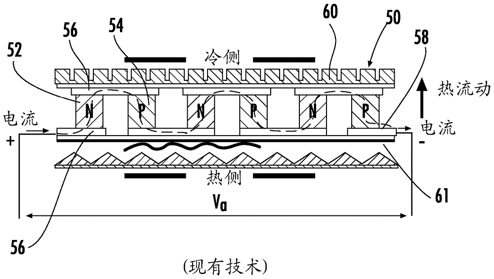
[0023] Traditional TE materials, such as BiTe (bismuth-tellurium), have low operating temperatures, which limit their use in automotive applications and / or require equipment cooling exhaust streams. Several classes of TE materials have been discovered in recent years that provide high performance over a broad temperature range. Among these materials, some half-Hurst (HH) compounds are...


PUM


Abstract

A thermoelectric power generation (TEG) unit configured to be integrated into the exhaust system of a vehicle includes a plurality of thermoelectric power generator modules, each comprising an electrically interconnected plurality of p-type and n-type thermoelectric material legs, each leg extending between a substrate on a hot side and a substrate on a cold side of the module, wherein the thermoelectric materials for the legs are half-Heusler compounds having a thermoelectric figure of merit (ZT) greater than 1.0.

Description

[0001] Regarding Related Applications and Priority Claims [0002] This application is a formal filing of, and claims priority from, co-pending US Provisional Application No. 61 / 912,151, filed December 5, 2013, the entire disclosure of which is incorporated herein by reference. [0003] Statement of Government Interest [0004] This invention was made with government support under Grant DE-EE0004840 awarded by the US Department of Energy. The government has certain rights in this invention. technical field [0005] The present disclosure relates to thermoelectric generators (TEGs), and in particular to TEGs for use in motor vehicles. Background technique [0006] The fuel efficiency of motor vehicles can be improved by integrating a thermoelectric generator (TEG) in the exhaust system. TEG uses the Seebeck effect to convert waste heat from internal combustion engines into electricity. A typical TEG includes a hot-side heat exchanger, a cold-side heat exchanger, thermoele...

Claims


Application Information

Patent Timeline
IPC IPC(8): H01L35/02H01L35/12H01L35/34
CPCC22C28/00H10N10/80H10N10/853H10N10/852H10N10/01H10N10/17
Inventor G.萨姆索尼德策B.科青斯基
Owner ROBERT BOSCH GMBH
Why Eureka
Try Eureka