
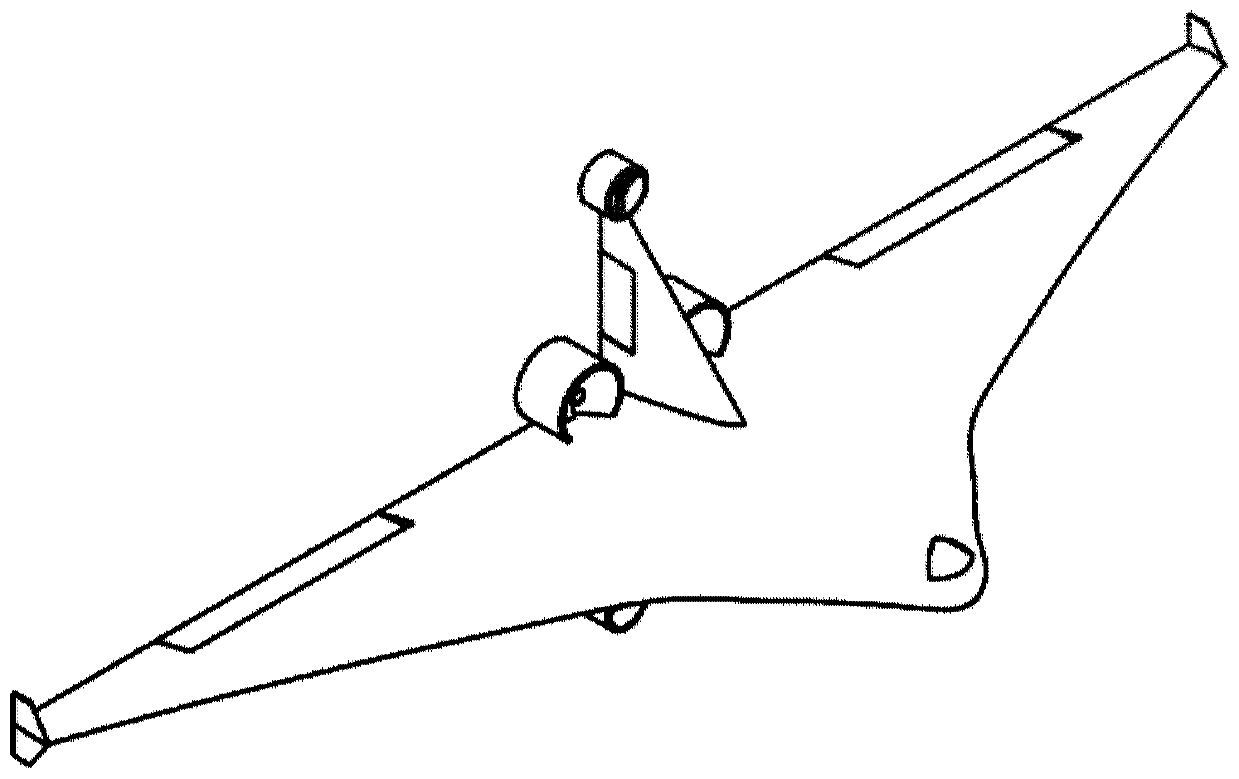
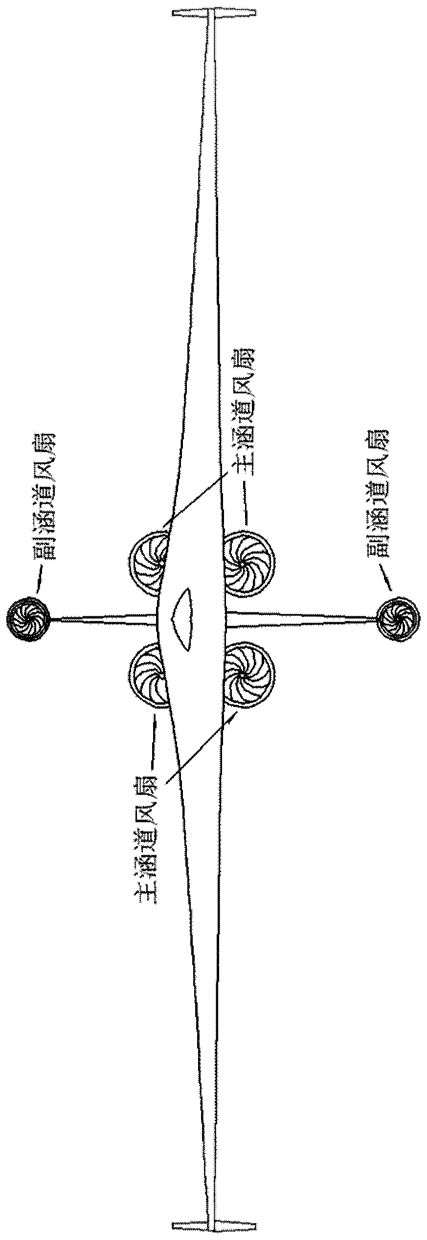
A flying-wing ducted fan vertical take-off and landing UAV

A ducted fan, vertical take-off and landing technology, applied in vertical take-off and landing aircraft, rotorcraft, aircraft parts, etc., can solve the problems of poor maneuverability, no fixed-point hovering operation ability, weak stealth ability, etc. Strong, excellent cruising ability, good practical benefits

Active Publication Date: 2020-04-07
INST OF ENGINEERING THERMOPHYSICS - CHINESE ACAD OF SCI
View PDF6 Cites 0 Cited by
  • Summary
  • Abstract
  • Description
  • Claims
  • Application Information

AI Technical Summary

Problems solved by technology

[0005] In order to overcome the shortcomings of traditional fixed-wing drones that rely too much on the airport runway for take-off and landing, poor maneuverability, no fixed-point hovering operation capability, complex internal transmission and control structure, low space utilization rate of the whole machine, and weak stealth ability

Method used


Image

  • A flying-wing ducted fan vertical take-off and landing UAV
  • A flying-wing ducted fan vertical take-off and landing UAV
  • A flying-wing ducted fan vertical take-off and landing UAV

Examples


Embodiment Construction

[0021] The present invention proposes a flying-wing ducted fan vertical take-off and landing drone, including a fuselage, wings and a ducted fan. The ducted fan is arranged at the tail of the aircraft. It takes off and lands with a tail seat layout on the ground, and enters the cruising flight attitude by tilting the whole fuselage after take-off.

[0022] New distributed layout, energy management and distribution is the focus of the design, in order to have higher efficiency of ducted fans in different flight stages and flight states, so according to the flight characteristics of different stages, the design is equipped with ducts with different performances fan. When taking off and landing with the nose up, the required fan thrust is relatively large, so all the ducted fans of the whole machine work together. When cruising and flying with the normal attitude of the fuselage, the whole machine has excellent lift-drag characteristics. At this time, only part of the ducted fan...


PUM


Abstract

The invention discloses a vertical take-off and landing type flying wing layout unmanned aerial vehicle, which includes a fuselage, wings, upper and lower tails and ducted fans, and is characterized in that it uses distributed ducted fan power to take off in a tailstock layout, and the fuselage and The main ducted fan is set at the tail of the wing, which is used for lift and attitude control during vertical take-off and landing, and provides cruising flight thrust. power. The UAV has a flexible vertical take-off and landing capability, and can complete the take-off and landing process without relying on the airport runway. At the same time, it has excellent cruise efficiency, speed and range. High structural utilization and other characteristics.

Description

technical field [0001] The invention relates to a flying-wing distributed ducted fan UAV, in particular to a flying-wing ducted fan vertical take-off and landing UAV. Background technique [0002] As we all know, if an airplane wants to overcome gravity and fly in the sky, it needs to pass through the air with different flow speeds on the upper and lower surfaces of the wing to generate a pressure difference to form the upward lift force that lifts the airplane. In this case, when the aircraft takes off, it needs at least hundreds of meters or even thousands of meters to accelerate. Due to the limitations of aircraft design and materials, aircraft takeoff can only be carried out on relatively flat ground or runways, and airports have emerged as the times require. Usually, a military airport includes one or more runways, taxiways, aprons, operational command rooms, etc. These components occupy a large amount of land area, so the area of ​​an airport is more than 3 square kilo...

Claims


Application Information

Patent Timeline
Patent Type & Authority Patents(China)
IPC IPC(8): B64C29/02B64C27/32B64C3/00
CPCB64C3/00B64C27/32B64C29/02B64U30/20
Inventor 曾冠南沈思颖曹华振闫晓鹏赵大林周礼洋李晨
Owner INST OF ENGINEERING THERMOPHYSICS - CHINESE ACAD OF SCI
Learn More