Gas, liquid and power conversion system

A gas and liquid technology, applied in the field of gas, liquid and power conversion systems, can solve the problems of energy loss, unsustainable torque state of the transmission rod and crankshaft, poor energy conversion efficiency, etc., and achieve high energy conversion efficiency

Inactive Publication Date: 2016-12-07
唐翊翃
View PDF0 Cites 4 Cited by
  • Summary
  • Abstract
  • Description
  • Claims
  • Application Information

AI Technical Summary

Problems solved by technology

[0002] At present, gas turbines and hydraulic turbines cannot form a sealed pressure chamber during operation, and energy will be lost from the gap
During

Method used


Image

  • Gas, liquid and power conversion system
  • Gas, liquid and power conversion system
  • Gas, liquid and power conversion system

Examples


Embodiment 1

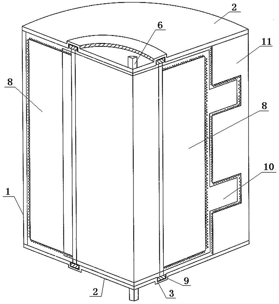
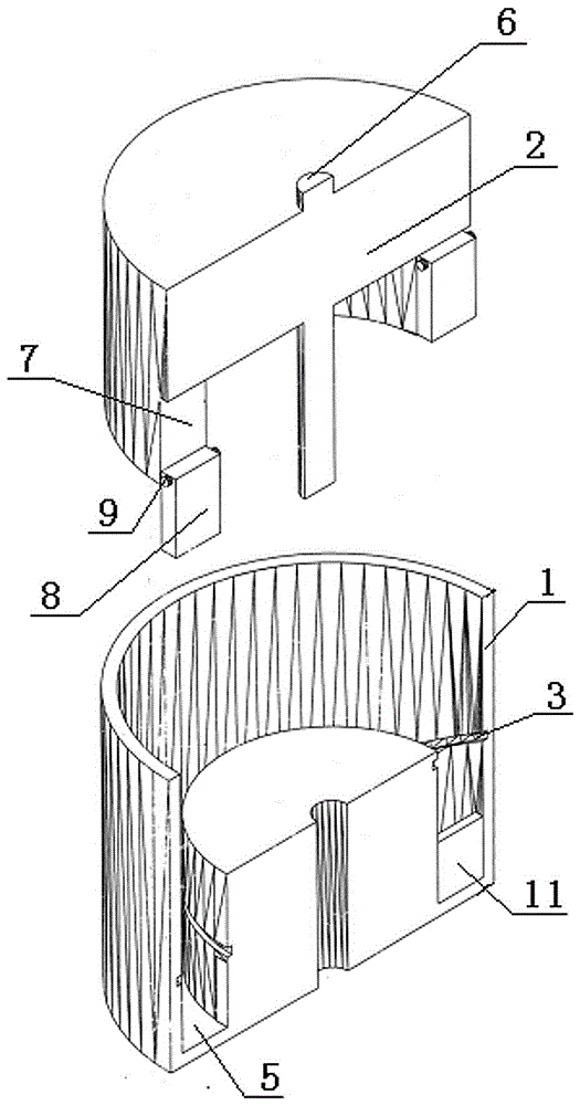
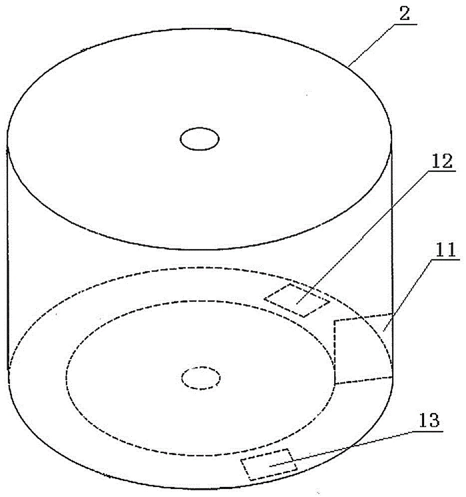
[0017] Figure 1 ~ Figure 4 , provides the figure of Embodiment 1 of the present invention. see Figure 1 ~ Figure 4 , In the present embodiment 1 gas, liquid and power conversion system, the two ends of the cylindrical stator 1 respectively have stator seats 2 fitted therewith. There are respectively eccentric annular concave guide grooves 3 at the corresponding positions of the two stator seats. There is an annular cavity 5 between the rotor 4 located in the stator and the stator. The two ends of the rotor shaft 6 are respectively installed on the corresponding stator bases and relatively rotated. Three sliding slots 7 communicating with the annular cavity are provided on the rotor at equal distances in the axial direction. A slide block 8 that can slide along the chute is housed in each chute. Bearings 9 that extend into the eccentric annular concave guide grooves on the corresponding stator seat and can rotate and slide along the eccentric annular concave guide groove...

Embodiment 2

[0021] Figure 5 , Image 6 Figure 2 of this embodiment is given. see Figure 5 , Image 6 In this embodiment 2, there is an annular cavity 5 between the rotor 2 in the cylindrical stator 1 and the stator. Corresponding positions on the stator have undulating annular concave guide grooves 3 respectively. The two ends of the rotor shaft 6 are mounted on the corresponding stators respectively and rotate relative to each other. Two slide grooves 7 with one end communicating with the annular cavity are arranged at equal distances on the rotor. A slide block 8 that can slide along the chute is housed in each chute. The bearings 9 on the two ends of the slider extend into corresponding undulating annular concave guide grooves on the stator respectively and can slide along the undulating annular concave guide grooves. In the annular cavity between the stator and the rotor, there is a pressure resistance card 11 mounted on the inner wall of the stator and cooperating with the ro...


PUM


Abstract

The invention relates to a gas, liquid and power conversion system. A ring-shaped cavity is formed between a rotor and a stator, annular concave guide grooves are respectively formed in corresponding positions of the stator, at least two chutes which communicate with the ring-shaped cavity are equidistantly formed in the rotor, a sliding block is arranged in each chute and can slide along the chute, two ends of each sliding block respectively extend into the corresponding annular concave guide grooves in the stator and can slide along the annular concave guide grooves, a pressure stopping card which is arranged on the inner wall of the stator, is matched with the rotor and is used for stopping circulation of gas or liquid is arranged in the ring-shaped cavity between the stator and the rotor, and an inlet and an outlet which respectively communicate with the ring-shaped cavity are formed in the stator and positioned in two sides of the pressure stopping card, so that a one-way flow channel which extends from the inlet to the outlet through the ring-shaped cavity is formed. The stress work state of the gas, liquid and power conversion system can always be optimal, and the energy conversion efficiency is high.

Description

Technical field: [0001] The invention relates to a gas, liquid and power conversion system that can efficiently convert air pressure and hydraulic pressure into power, and can also use power to efficiently convert gas and liquid into air pressure and hydraulic pressure. Background technique: [0002] At present, gas turbines and water turbines cannot form sealed pressure chambers during operation, and energy will be lost from the gaps. During the operation of the air pump, the transmission rod and the crankshaft cannot maintain a good torque state, resulting in poor energy conversion efficiency. Invention content: [0003] The purpose of the present invention is to overcome the disadvantages and provide a gas, liquid and power conversion system with high energy conversion efficiency. [0004] The purpose of the present invention is achieved like this: [0005] In the gas, liquid and power conversion system of the present invention, there is an annular cavity between the ...

Claims


Application Information

Patent Timeline
IPC IPC(8): F01C1/344F03C2/30
CPCF01C1/344F03C2/30F03C2/304
Inventor 唐翊翃唐立
Owner 唐翊翃
Why Eureka
Try Eureka