Oil-gas separator assembly

An oil and gas separator and assembly technology, which is applied in the direction of machines/engines, engine components, mechanical equipment, etc., can solve the problems of difficult casting and processing, deep oil and gas separators, low separation efficiency, etc., to reduce maintenance costs, The effect of reducing air pollution and prolonging the cleaning cycle

Inactive Publication Date: 2016-12-07
WEICHAI POWER CO LTD
View PDF7 Cites 3 Cited by
  • Summary
  • Abstract
  • Description
  • Claims
  • Application Information

AI Technical Summary

Problems solved by technology

Although this solution can achieve the purpose of filtering large-particle oil droplets, it requires a long stud to fix the filter element and the oil-gas separator cover, resulting in deep threaded holes inside the oil-gas separator body, making casting and processing difficult. And the gas passes through the filter element from the inside to the outside, and the bottom of the filter element is sealed, resulting in an oil accumulation point at the low point between the filter element and the cavity wall (such as figure 2 As shown), the oil return is not smooth; in addition, there are only two partitions 6 on the inner wall of the filter chamber 8, and the separation efficiency is low, resulting in low overall separation efficiency

Method used


Image

  • Oil-gas separator assembly
  • Oil-gas separator assembly
  • Oil-gas separator assembly

Examples


Embodiment Construction

[0018] Exemplary embodiments of the present disclosure will be described in more detail below with reference to the accompanying drawings. Although exemplary embodiments of the present disclosure are shown in the drawings, it should be understood that the present disclosure may be embodied in various forms and should not be limited by the embodiments set forth herein. Rather, these embodiments are provided for more thorough understanding of the present disclosure and to fully convey the scope of the present disclosure to those skilled in the art.

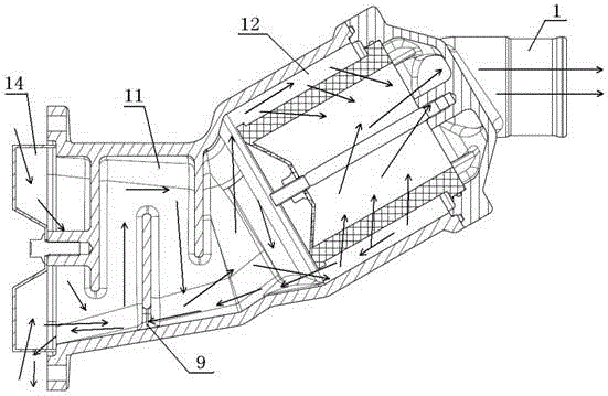
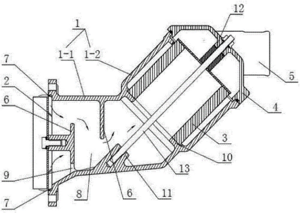
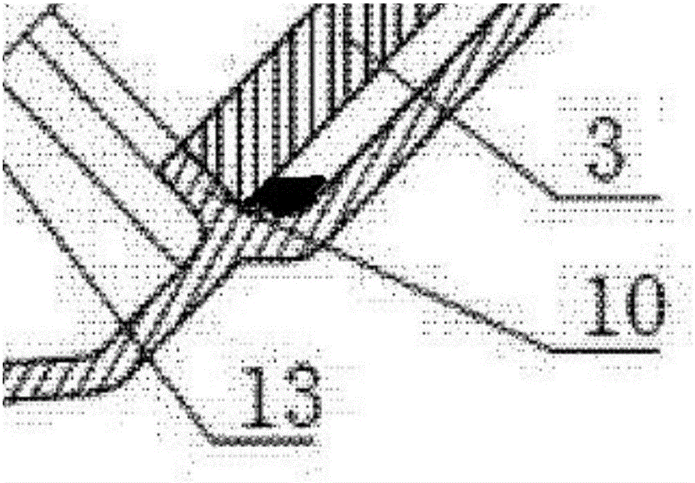
[0019] According to the embodiment of the present invention, such as image 3 and Figure 4 As shown, an oil-air separator assembly includes an oil-air separator housing 1 sealingly connected to the crankcase. The oil-air separator housing 1 includes an integrally formed first filter section 3-1 and a second obliquely upwardly disposed Filter section 3-2, the inner cavity of the second filter section 3-2 is the second filter cavit...


PUM


Abstract

The invention relates to an oil-gas separator assembly. Large-particle oil drops are pre-separated through the matching of oil baffles and a plurality of partition plates, and then, relatively-small-particle oil mists are separated by using a filter element, so that the oil-gas separation effect can be greatly improved, and air pollution can be reduced. The filter element of the oil-gas separator assembly can be directly mounted on an upper sealing cover, gaps exist inside the filter element and a filter cavity, a gas penetrates from the outside to the inside of the filter element, and the bottom of the filter element is closed, so that oil accumulation points generated at the filter element and a low point of the wall of the cavity are eliminated, oil is returned smoothly, the clearing period of the filter element is prolonged, and furthermore, the maintenance cost is reduced.

Description

technical field [0001] The invention relates to an oil-gas separator assembly. Background technique [0002] The oil-gas mixture in the crankcase of a diesel engine contains large-particle oil droplets. Only the filter element is used to separate the oil and gas, and the large-particle oil droplets are not pre-separated, which may easily cause the filter element to be blocked. Frequent cleaning and replacement of the filter element is required, and the service life of the filter element is low. Causes the disadvantage of high maintenance cost. For this problem, the device that pre-separates large-particle oil droplets is usually added. For example, the Chinese invention patent whose notification number is CN103470342B adds an oil baffle plate for filtering large-particle oil droplets on the oil-gas separator housing, such as figure 1 As shown, the oil baffle plate can prevent large-particle oil droplets from entering the inner cavity of the oil-gas separator, and the oil-ga...

Claims


Application Information

Patent Timeline
Patent Type & Authority Applications(China)
IPC IPC(8): F01M13/04
CPCF01M13/04F01M2013/0433F01M2013/0438
Inventor 蔡海杰吕顺王少帅
Owner WEICHAI POWER CO LTD
Why Eureka
Try Eureka