Control valve group for harvester
A technology for controlling valves and harvesters, which is applied in the hydraulic field, can solve problems such as operator fatigue, large range of motion, and complicated operation of the operator, and achieve the effects of reducing research and development costs and facilitating installation
- Summary
- Abstract
- Description
- Claims
- Application Information
AI Technical Summary
Problems solved by technology
Method used
Image

Examples
Embodiment 1
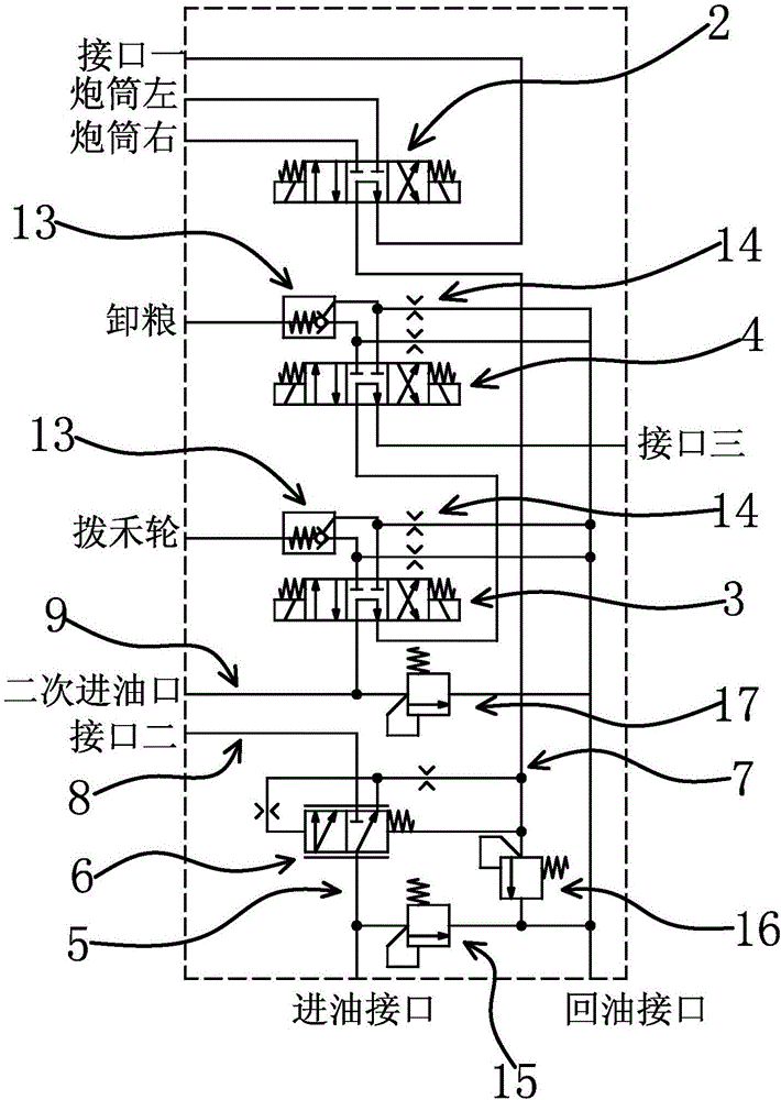
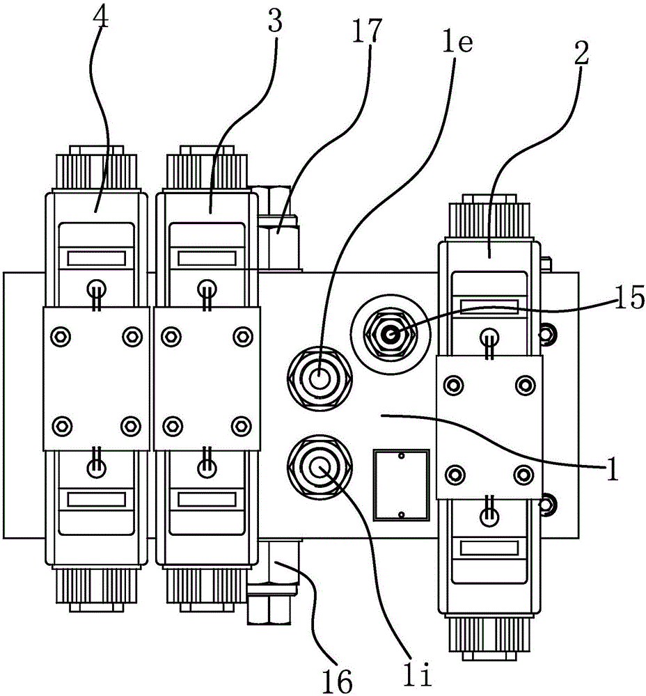
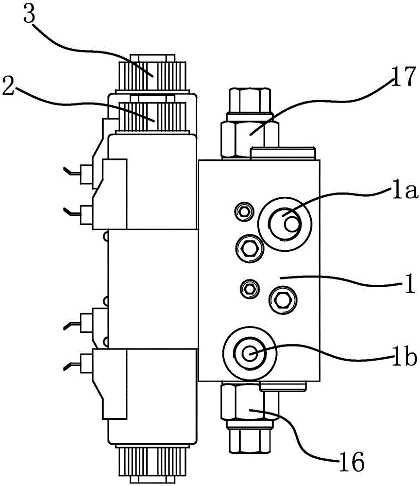
[0036] The control valve group of the harvester includes valve body 1, oil inlet interface 1a, oil return interface 1b, electromagnetic reversing valve one 2, electromagnetic reversing valve two 3, electromagnetic reversing valve three 4, diverter valve 6, interface one 1c , interface two 1d, secondary oil inlet 1e and interface three 1f.
[0037] Specifically, as figure 2 As shown, the first electromagnetic reversing valve 2 , the second electromagnetic reversing valve 3 , and the third electromagnetic reversing valve 4 are all arranged on the valve body 1 , and the diverter valve 6 is located in the valve body 1 . In this embodiment, the first electromagnetic reversing valve 2 , the second electromagnetic reversing valve 3 and the third electromagnetic reversing valve 4 are three-position four-way M-type electromagnetic valves.
[0038] like figure 1 As shown, the oil inlet port 1a is connected to the diverter valve 6 through the main oil circuit 5, and the diverter valv...
Embodiment 2
[0044] This embodiment discloses another application mode of the control valve group of the harvester in the hydraulic control system, such as Figure 11 As shown, in this embodiment, the conical screw plug 2 12 is removed so that the secondary oil inlet passage 9 can directly communicate with the control oil passage 2 8, and then the interface 2 1d and the secondary oil inlet 1e are blocked, and the interface 1 1c The oil return interface 1b is connected in the valve body 1, and the interface 3 1f is connected to the oil inlet of the header steering independent control valve 21. This connection method is suitable for, for example, the attached Figure 12 The hydraulic control system of the traditional mechanical control shown is modified to realize electric control and mechanical control, and the cost is low; but the steering cylinder 23 cannot be linked with the header cylinder 22, the reel cylinder 19 and the grain unloading cylinder 20.
Embodiment 3
[0046] The technical solution in this embodiment is basically the same as the technical solution in Embodiment 1. The difference is that in this embodiment, the secondary oil inlet passage 9 and the control oil passage 2 8 are connected, and there is a through valve body at the connection between the two. 1, the plugging hole is fixedly connected with a plugging piece, and the plugging piece can block the secondary oil inlet passage 9 and the control oil passage two 8. Install a plugging piece with a plugging head on the plugging hole, and block the secondary oil inlet passage 9 and the control oil passage 2 8 through the plugging head; install a plugging piece without a plugging head on the plugging hole , It is possible to connect the blocked secondary oil inlet passage 9 with the control oil passage two 8.
PUM
 Abstract
Description
Claims
Application Information
 - R&D
- Intellectual Property
- Life Sciences
- Materials
- Tech Scout
- Unparalleled Data Quality
- Higher Quality Content
- 60% Fewer Hallucinations
Browse by: Latest US Patents, China's latest patents, Technical Efficacy Thesaurus, Application Domain, Technology Topic, Popular Technical Reports.
© 2025 PatSnap. All rights reserved.Legal|Privacy policy|Modern Slavery Act Transparency Statement|Sitemap|About US| Contact US: help@patsnap.com