

Heat dissipation shockproof device of filter for high-voltage harmonic treatment
A high-voltage harmonic and shock-proof device technology, which is applied in the use of liquid cooling for modification, cooling/ventilation/heating modification, electrical components, etc. Good fixing effect, good heat dissipation effect and high safety effect
- Summary
- Abstract
- Description
- Claims
- Application Information
AI Technical Summary
Problems solved by technology
Method used
Image


Examples
Embodiment 1
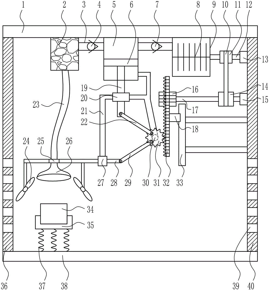
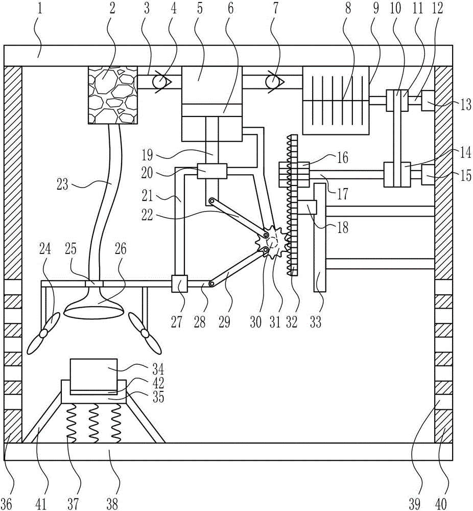
[0033] A filter heat dissipation and anti-shock device for high-voltage harmonic processing, such as Figure 1-4As shown, it includes top plate 1, drying box 2, first cold air pipe 3, first one-way valve 4, cylinder body 5, piston 6, second one-way valve 7, stirring rod 8, storage bin 9, flat belt 10 , small pulley 11, first rotating shaft 12, first bearing seat 13, large pulley 14, second bearing seat 15, first gear 16, second rotating shaft 17, slider 18, lifting rod 19, first sliding sleeve 20, Strut 21, first connecting rod 22, second cold air pipe 23, fan 24, fixed ring 25, air jet bucket 26, second sliding sleeve 27, moving rod 28, second connecting rod 29, motor 30, second gear 31 , rack 32, slide rail 33, filter 34, placement groove 35, left support 36, spring 37, base plate 38 and right support 40, base plate 38 top is provided with left support 36, spring 37 and right support successively from left to right 40, the left bracket 36 and the right bracket 40 are provid...
PUM
 Abstract
Description
Claims
Application Information