A flue gas waste heat recovery device

A recovery device and flue gas waste heat technology, applied in preheating, liquid degassing, indirect heat exchangers, etc., can solve the waste of flue gas waste heat resources, etc., to improve waste heat recovery efficiency, promote coordinated development, and low cost Effect

Active Publication Date: 2018-10-02
NANJING BAIYUN CHEM ENVIRONMENTAL MONITORING
View PDF7 Cites 1 Cited by
  • Summary
  • Abstract
  • Description
  • Claims
  • Application Information

AI Technical Summary

Problems solved by technology

[0003] The purpose of the present invention is to provide a flue gas waste heat recovery device with simple structure, good control effect and high flue gas waste heat recovery utilization rate, so as to solve the waste of a large amount of flue gas waste heat resources in the boiler smoke exhaust system in the prior art

Method used


Image

  • A flue gas waste heat recovery device

Examples


Embodiment 1

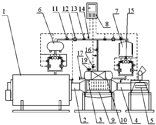
[0016] Embodiment 1: as figure 1 As shown, a flue gas waste heat recovery device includes a gas boiler 1, a high-temperature flue gas exhaust pipe 2, a flue gas heat exchanger 3, a softened water storage device 7, a low-temperature flue gas pipe 4, a low-temperature flue gas desulfurization discharge device 5, Hot water deaerator 6 and automatic control cabinet 8, the gas boiler 1 is connected to the high-temperature flue gas inlet of the flue gas heat exchanger 3 through the high-temperature flue gas exhaust pipe 2, and the low-temperature flue gas outlet of the flue gas heat exchanger 3 passes through The low-temperature flue gas pipeline 4 is connected to the low-temperature flue gas desulfurization discharge device 5, the water supply port of the flue gas heat exchanger 3 is connected to the softened water storage device 7 through the water supply pipe network, and the water outlet of the flue gas heat exchanger 3 is connected to the water supply port through the water supp...

Embodiment 2

[0017] Embodiment 2: as figure 1 As shown, as an improvement of the present invention, the finned superconducting heat pipe is made of polytetrafluoroethylene. The rest of the structures and advantages are exactly the same as in Embodiment 1.

Embodiment 3

[0018] Embodiment 3: as figure 1 As shown, as an improvement of the present invention, an induced draft fan is provided between the low-temperature flue gas desulfurization discharge device 5 and the low-temperature flue gas pipeline 4, and the air inlet of the induced draft fan is connected to the low-temperature flue gas pipeline 4. The air outlet is connected to the low-temperature flue gas desulfurization discharge device 5 . The rest of the structures and advantages are exactly the same as in Embodiment 1.


PUM


Abstract

The invention relates to a smoke waste heat recovery device. The smoke waste heat recovery device comprises a gas boiler, a high-temperature smoke exhaust pipeline, a smoke heat exchanger, a softened water storage device, a low-temperature smoke pipeline, a low-temperature smoke desulfurization exhaust device, a hot water deaerator and an automatic control cabinet. The gas boiler is connected with a high-temperature smoke inlet of the smoke heat exchanger through the high-temperature smoke exhaust pipeline. A low-temperature smoke outlet of the smoke heat exchanger is connected with the low-temperature smoke desulfurization exhaust device through the low-temperature smoke pipeline. A water supply inlet of the smoke heat exchanger is connected with the softened water storage device through a water replenishing pipe network. A water outlet of the smoke heat exchanger is connected with a boiler water supply pipe network through a heat supply water pipe. The softened water storage device is connected with the hot water deaerator through the boiler water supply pipe network. The hot water deaerator is connected with a water inlet of the gas boiler. The automatic control cabinet is electrically connected with the smoke heat exchanger, the softened water storage device, the low-temperature smoke desulfurization exhaust device and the hot water deaerator so that automatic operation of whole smoke waste heat recovery can be achieved. The smoke waste heat recovery device is high in smoke waste heat recovery utilization rate.

Description

technical field [0001] The invention relates to a flue gas waste heat recovery device, in particular to a flue gas waste heat recovery device for a gas boiler. Background technique [0002] In the operation of gas-fired boilers, the loss of flue gas waste heat resources is the most important loss of waste heat resources, accounting for 60% to 70% of the loss of boiler waste heat resources. The exhaust gas temperature is the main factor affecting the loss of flue gas waste heat resources. At present, the actual exhaust gas temperature of enterprises using boilers in my country is generally higher than the design temperature. Generally, every 10°C reduction in exhaust gas temperature reduces the loss of flue gas waste heat resources by 0.6%. ~1%, the corresponding saving of energy consumption is 1.2%~2.4%, and the economic benefit is remarkable. Therefore, in the context of the current implementation of energy-saving and emission-reduction policies, it is urgent to develop a f...

Claims


Application Information

Patent Timeline
Patent Type & Authority Patents(China)
IPC IPC(8): F22B1/18F22B35/00F23J15/02F22D1/50F22D11/00F28D7/00
CPCF22B1/18F22B35/00F22D1/50F22D11/00F23J15/022F28D7/00
Inventor 胡家富冯建琳党元军王芸王海珍刘婷婷
Owner NANJING BAIYUN CHEM ENVIRONMENTAL MONITORING
Why Eureka
Try Eureka