Oil separator

An oil separator and chamber technology, which is used in refrigeration components, refrigerators, lighting and heating equipment, etc., can solve the problems of large resistance, low separation efficiency, and reduced separation efficiency, so as to increase the separation path and enhance separation. effect, effect of reducing exhaust resistance

Active Publication Date: 2016-12-07
TRANE AIR CONDITIONING SYST (CHINA) CO LTD
View PDF6 Cites 7 Cited by
  • Summary
  • Abstract
  • Description
  • Claims
  • Application Information

AI Technical Summary

Problems solved by technology

At present, the large-scale central air-conditioning system mainly has two types: centrifugal type and filter type. The centrifugal type oil separator is suitable for separating large-diameter oil droplets, and the separation efficiency is greatly reduced at low airflow speeds. The filter-type separator is suitable for separating small-diameter oil droplets, with large resistance. It is difficult to guarantee the cleanliness of the filter screen during the production process
[0005] The existing centrifugal oil separator has low separation efficiency at low load and low-speed airflow, and the separation effect on small-sized oil droplets is not good, while the filter type oil has high resistance, low cleanliness and low separation efficiency, which makes Lubricating oil is brought into the condenser or even the evaporator, which affects the heat exchange effect of the unit and thus affects the energy efficiency of the whole machine

Method used


Image

  • Oil separator
  • Oil separator
  • Oil separator

Examples


Embodiment Construction

[0029] The present invention will be further described below in conjunction with accompanying drawing and embodiment:

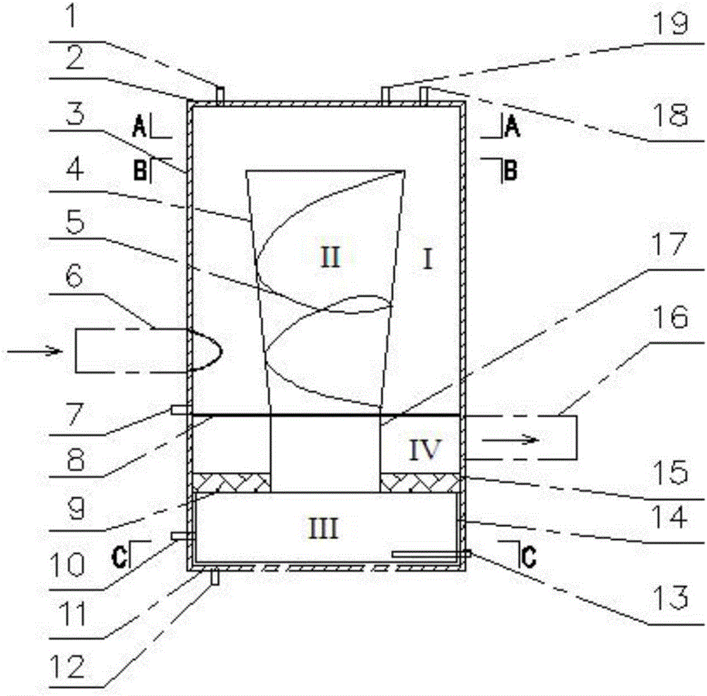
[0030] Such as figure 1 The shown oil separator includes an outer cylinder body 3. The outer cylinder body 3 specifically includes a cylinder wall, an upper end cover 2 located at the upper end of the cylinder wall, and a lower end plate 11 located at the lower end of the cylinder wall. Air inlets and Exhaust port, welding intake pipe 6 on the air inlet, welding exhaust pipe 16 on the exhaust port.

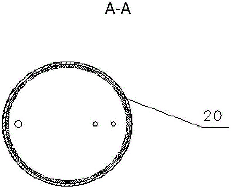
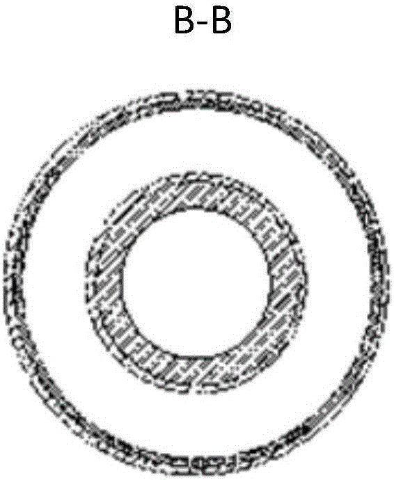
[0031] A baffle 8 is arranged horizontally from top to bottom in the outer cylinder 3 (such as Figure 4 As shown), the filter layer 15, the baffle 8 divides the outer cylinder 3 into two parts, the double cyclone centrifugal separator and the filter and muffler separator, the baffle 8 has a round hole in the middle, and the outer cylinder above the baffle 8 The body 3 is provided with an inner circular table cavity 4, which is welded with the baffle plate 8. T...


PUM


Abstract

The invention relates to an oil separator. The oil separator comprises an outer barrel, a baffle arranged in the outer barrel and a filter screen layer. An inner circular truncated cone cavity is formed in the position, above the baffle, in the outer barrel. A first area chamber is formed between the inner circular truncated cone cavity and the outer barrel. A second area chamber communicating with the first area chamber is formed by the inner circular truncated cone cavity. A third area chamber is formed below the filter screen layer. An inner barrel enabling the second area chamber to communicate with the third area chamber is arranged between the baffle and the filter screen layer. A fourth area chamber is formed between the inner barrel and the outer barrel. The third area chamber communicates with the fourth area chamber through the filter screen layer. An air inlet is located in the first area chamber, and an exhaust opening is located in the fourth area chamber. According to the oil separator, dual-travel cyclone centrifugal separation and filter screen filtering separation are set, the four chambers are formed, the air flow direction is changed many times, the number of paths separated by the oil separator is increased, and the separation effect is enhanced; and the exhaust opening is formed in the lower middle portion of the oil separator, and therefore the distance of an exhaust pipe is shortened, exhaust resistance and vibration are reduced, and the energy efficiency of a unit can be improved easily.

Description

technical field [0001] The invention relates to the technical field of refrigeration, in particular to an oil separator for separating oil mixed in gaseous refrigerant. Background technique [0002] Lubricating oil plays a vital role in the compressor of the refrigeration system. It not only provides lubrication and cooling for the rotor, but also the oil film can seal the gap between the rotor and the compressor shell, thereby limiting the leakage of high-pressure refrigerant gas. Improved compressor efficiency. [0003] Since the lubricating oil is mixed in the refrigerant system, it is inevitably brought into the condenser or even the evaporator, and an oil film is formed on the surface of the heat exchange tube in the container, which increases the heat transfer resistance and reduces the heat transfer coefficient, thus affecting the heat transfer effect and cooling efficiency. The oil separator is to separate the oil from the high-pressure refrigerant gas discharged f...

Claims


Application Information

Patent Timeline
Patent Type & Authority Applications(China)
IPC IPC(8): F25B43/02
CPCF25B43/02
Inventor 沈海英
Owner TRANE AIR CONDITIONING SYST (CHINA) CO LTD
Why Eureka
Try Eureka