Test device for burning speed/burning temperature of solid propellant and test method thereof

A solid propellant and testing device technology, applied in chemical analysis by combustion, can solve problems such as errors, complex processing of experimental data, uncalculated, etc., and achieve the effect of solving the large proportion of heat loss, accurate measurement and calculation, and reliable data.

Active Publication Date: 2016-12-07
UNIV OF SCI & TECH OF CHINA
View PDF16 Cites 20 Cited by
  • Summary
  • Abstract
  • Description
  • Claims
  • Application Information

AI Technical Summary

Problems solved by technology

However, since the test of the airtight explosive device requires complex processing of the experimental data, and the test method is based on the theory of gunpowder combustion, it needs to go through a series of assumptions and simplifications, which brings certain errors
In addition, at present, empirical formulas are generally used to correct the heat loss of the closed blaster test, without considering the influence of pressure and radiation heat transfer changes in the propellant combustion stage on the heat loss process, less consideration is given to the heat transfer between the gas and the inner wall of the closed blaster, and Influence of Heat Loss on the Propellant Flame Temperature in a Sealed Exploser
The literature "Study on Measuring Propellant Burning Velocity at High Pressure by Closed Burner Method" pointed out that although the working time of the closed burner is very short, the pressure loss caused by the loss of heat diss

Method used


Image

  • Test device for burning speed/burning temperature of solid propellant and test method thereof
  • Test device for burning speed/burning temperature of solid propellant and test method thereof
  • Test device for burning speed/burning temperature of solid propellant and test method thereof

Examples


Embodiment Construction

[0042] The following examples are a further description of the content of the present invention as an explanation of the technical content of the present invention, but the essential content of the present invention is not limited to the following examples, those of ordinary skill in the art can and should know any Simple changes or replacements of the essential spirit of the invention shall fall within the scope of protection required by the present invention.

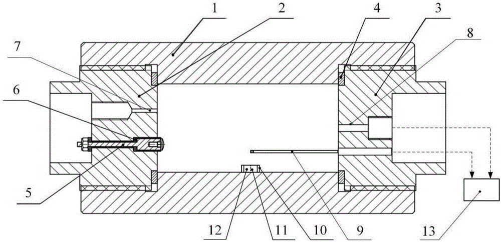
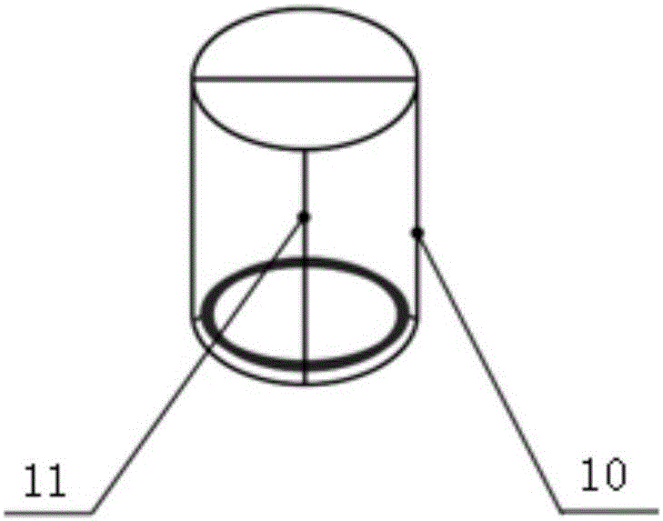
[0043] Such as figure 1 , figure 2As shown, a test device for solid propellant burning rate / burning temperature, comprising a constant volume burner body 1, a plug 2 and a plug 2 3 arranged at both ends of the constant volume burner body 1, The ignition electrode 5 and the pressure relief valve 7 on the head one 2, and the temperature sensor 9 and the pressure sensor 8 arranged on the plug two 3;

[0044] The constant-volume burner body 1 is a cylindrical chamber structure, which is manufactured by ultra-high press...


PUM


Abstract

The invention discloses a test device for burning speed/burning temperature of a solid propellant and a test method thereof. The test device comprises a constant volume burner main body, a first plug, a second plug, an ignition electrode, a decompression valve, a temperature sensor and a pressure sensor, wherein the ignition electrode and the decompression valve are arranged on the first plug; the temperature sensor and the pressure sensor are arranged on the second plug; the constant volume burner main body has a cylindrical chamber structure; one end of the constant volume burner main body is connected with the first plug through a thread while the other end is connected with the second plug through the thread; a clamping device is arranged in the constant volume burner main body; a propellant grain is fixed in the clamping device; a data collecting processing unit is arranged on the outer side of the constant volume burner main body; the data collecting processing unit is respectively connected with the pressure sensor and the temperature sensor. The test device provided by the invention can meet the requirement of propellant energy quantitative test, can simulate the high pressure environment of solid propellant application and can acquire the burning speed and burning temperature of the propellant under high pressure state, so that a reliable design input is supplied for the research on the propellant.

Description

technical field [0001] The invention relates to a burning rate / burning temperature test device, in particular to a solid propellant burning rate / burning temperature test device and a test method thereof under airtight conditions, belonging to the field of solid propellant combustion performance testing. Background technique [0002] As a halon alternative fire extinguishing technology, the solid propellant fire extinguishing technology is a kind of solid reactant as a propellant, through a controlled rapid reaction, a large amount of inert gas products (such as nitrogen, water vapor and CO 2 etc.) to drive the release of the fire extinguishing medium to achieve the effect of extinguishing a fire. This technology has been widely used in the field of fire extinguishing in small spaces in aircraft equipment due to its fast response speed, small footprint, storage at normal pressure, rich inert medium, and release of fire extinguishing medium within 100ms. However, the solid pr...

Claims


Application Information

Patent Timeline
IPC IPC(8): G01N31/12
CPCG01N31/12
Inventor 张和平张丹陆松曹承阳
Owner UNIV OF SCI & TECH OF CHINA
Why Eureka
Try Eureka