Motor rotating speed monitoring device

A technology of motor speed and monitoring device, which is applied to devices using optical methods, etc., can solve the problems of inaccurate motor detection accuracy, and achieve the effect of convenient use and accurate monitoring results.

Inactive Publication Date: 2016-12-07
HUNAN INSTITUTE OF ENGINEERING
View PDF4 Cites 0 Cited by
  • Summary
  • Abstract
  • Description
  • Claims
  • Application Information

AI Technical Summary

Problems solved by technology

In the prior art, the detection accuracy of the rotational speed of the motor is inaccurate, and in the spirit of excellence, continuous improvement is required

Method used


Image

  • Motor rotating speed monitoring device

Examples


Embodiment Construction

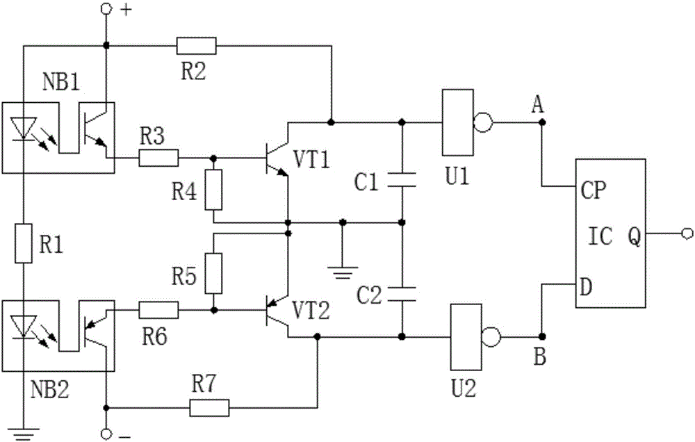
[0010] The present invention will be further described below in conjunction with accompanying drawing:

[0011] like figure 1 Shown: the present invention consists of a first optocoupler, a second optocoupler, a first resistor to a seventh resistor, a first capacitor, a second capacitor, a first triode, a second triode, a first NOT gate , the second NOT gate and double D flip-flops, the first resistor is 100Ω, the second resistor is 400Ω, the third resistor is 500Ω, the fourth resistor is 2kΩ, the fifth resistor is 27kΩ, the sixth resistor and the seventh resistor are both is 200Ω, the first capacitor is 300uf, the second capacitor is 470uf, the first transistor is a PNP transistor, the second transistor is an NPN transistor, and the first NOT gate and the second NOT gate are The NOT gate of model SN74AHC1G04 and the model of the double D flip-flop are MCR100-6 / 0.8A / 400V.

[0012] Further, the positive input end of the power supply is respectively connected to the first end ...


PUM


Abstract

The invention discloses a motor rotating speed monitoring device which is composed of a first optical coupler, a second optical coupler, first to seventh resistors, a first capacitor, a second capacitor, a first triode, a second triode, a first NOT gate, a second NOT gate and a double-D-trigger. The first resistor is 100ohm. The second resistor is 400ohm. The third resistor is 500ohm. The fourth resistor is 2kilohm. The fifth resistor is 27kilohm. The sixth resistor and the seventh resistor are 200ohm. The first capacitor is 300muf. The second capacitor is 470muf. The first triode is a PNP type triode. The second triode is an NPN type triode. The first NOT gate and the second NOT gate are the NOT gates of the model number of SN74HC1G04. The model number of the double-D-trigger is MCR100-6 / 0.8A / 400V. Compared with the devices in the prior art, rotating speed of a motor can be monitored in real time, and the optical couplers are used for sensing and the NOT gate circuits are used for control so that the monitoring result is accurate, use is convenient, and the device has popularization and application value.

Description

technical field [0001] The invention relates to a motor detection device, in particular to a motor speed monitoring device. Background technique [0002] A motor is an electromagnetic device that converts or transmits electrical energy according to the law of electromagnetic induction. In the circuit, it is represented by the letter M (the old standard is D). Its main function is to generate driving torque as a power source for electrical appliances or various machinery. A generator is represented by the letter G in the circuit. Its main function is to convert electrical energy into mechanical energy. In the prior art, the detection accuracy of the rotational speed of the motor is inaccurate, and continuous improvement is required in the spirit of excellence. Contents of the invention [0003] The object of the present invention is to provide a motor speed monitoring device in order to solve the above problems. [0004] The present invention achieves the above object ...

Claims


Application Information

Patent Timeline
Patent Type & Authority Applications(China)
IPC IPC(8): G01P3/36
CPCG01P3/36
Inventor 刘波秦春莲
Owner HUNAN INSTITUTE OF ENGINEERING
Why Eureka
Try Eureka