
Rail train displacement and speed detection system

A technology for speed detection and rail trains, applied in the field of rail transit, can solve problems such as increasing system stability, use and maintenance costs and difficulty, inability to obtain displacement and speed measurement results, and dynamic changes in track images, etc., to achieve simple parking accuracy judgment, Realize the effect of parking accuracy judgment and simplify the use requirements

Active Publication Date: 2016-12-07
SHANGHAI ELECTRIC THALES TRANSPORTATION AUTOMATION SYST CO LTD
View PDF5 Cites 29 Cited by
  • Summary
  • Abstract
  • Description
  • Claims
  • Application Information

AI Technical Summary

Problems solved by technology

However, when the operating environment and geographical environment along the line are complex, and the light intensity and ground texture change, the track image also changes greatly, and it is impossible to obtain stable displacement and velocity measurement results
Although the interference of ambient light can be avoided to a certain extent by adding non-visible light sources to supplement light, it also increases system stability, use and maintenance costs and difficulty
In addition, the height of the camera from the ground due to vibration and mechanical installation also causes dynamic changes in the track image, which affects the measurement accuracy, and requires separate equipment and methods for height measurement and compensation

Method used


Image

  • Rail train displacement and speed detection system
  • Rail train displacement and speed detection system

Examples


Embodiment Construction

[0040] The present invention will be further described below in conjunction with accompanying drawing.

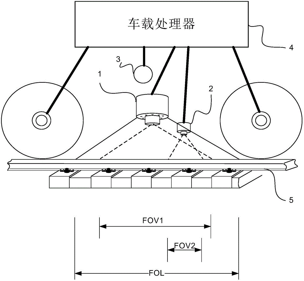
[0041] see figure 1 , The rail train displacement and speed detection system of the present invention includes a background detection camera 1, a target detection camera 2, an active light source 3 and an on-board processor 4 arranged on the train.

[0042] The on-board processor 4 is connected to the background detection camera 1 , the object detection camera 2 and the active light source 3 respectively. The installation height of the background detection camera 1 is higher than that of the target detection camera 2, and the light field FOL of the active light source 3 covers the field of view FOV1 of the background detection camera 1 facing the rail 5 and the field of view FOV2 of the target detection camera 2 facing the rail 5 .

[0043] The dual-set vision system of the background detection camera 1 and the target detection camera 2 cleverly solves the problem that a ...


PUM


Abstract

The invention discloses a rail train displacement and speed detection system. The system comprises a background detection camera, a target detection camera, an active light source and a vehicle-mounted processor, all of which are arranged on a train. The light field of the active light source covers the view field, directly facing a steel rail, of the background detection camera and the view field, directly facing the steel rail, of the target detection camera; the vehicle-mounted processor compares the movement offset of two frames of adjacent background images collected by the background detection camera and the movement offset of two frames of adjacent target images collected by the target detection camera, and a first displacement and a second displacement in one image capture of the train are calculated in combination with imaging plane and rail plane height values; the vehicle-mounted processor conducts weighting calculation on the first displacement and the second displacement, and real-time displacement and speed of the train are obtained. The system has the advantages of being high in reliability, high in detection precision, low in cost, easy and convenient to install and maintain and wide in application range.

Description

technical field [0001] The invention relates to the field of rail transportation, in particular to a displacement and speed detection system for rail trains. Background technique [0002] The existing train displacement and speed measurement systems mainly include the following types: [0003] 1) The method of converting the train displacement and speed by measuring the train wheel rotation combined with the wheel diameter. The measurement system sensor in this type of method needs to use a rotating mechanical structure, high installation requirements, poor accuracy in the low-speed range, and idling and slipping of the vehicle will cause measurement failure. [0004] The wheel diameter parameter is also an important factor leading to conversion errors, and the wheel diameter usually needs to be manually calibrated periodically or obtained through automatic calibration. The problem of manual input is that the wheel diameter value is fixed in a calibration period, which is ...

Claims


Application Information

Patent Timeline
IPC IPC(8): G01S11/12G01P3/68B61L25/02
CPCB61L25/021G01P3/68G01S11/12
Inventor 高翔
Owner SHANGHAI ELECTRIC THALES TRANSPORTATION AUTOMATION SYST CO LTD
Learn More