Current mode circuit of maximum current value

A technique of current maximum value and current mode

Inactive Publication Date: 2016-12-07
SHANGHAI HUAHONG GRACE SEMICON MFG CORP
View PDF5 Cites 7 Cited by
  • Summary
  • Abstract
  • Description
  • Claims
  • Application Information

AI Technical Summary

Problems solved by technology

[0011] 1. Complex structure
[0012] 2. High power consumption
[0013] 3. Occupies a large chip area

Method used


Image

  • Current mode circuit of maximum current value
  • Current mode circuit of maximum current value
  • Current mode circuit of maximum current value

Examples


Embodiment Construction

[0034] The implementation of the present invention is described below through specific examples and in conjunction with the accompanying drawings, and those skilled in the art can easily understand other advantages and effects of the present invention from the content disclosed in this specification. The present invention can also be implemented or applied through other different specific examples, and various modifications and changes can be made to the details in this specification based on different viewpoints and applications without departing from the spirit of the present invention.

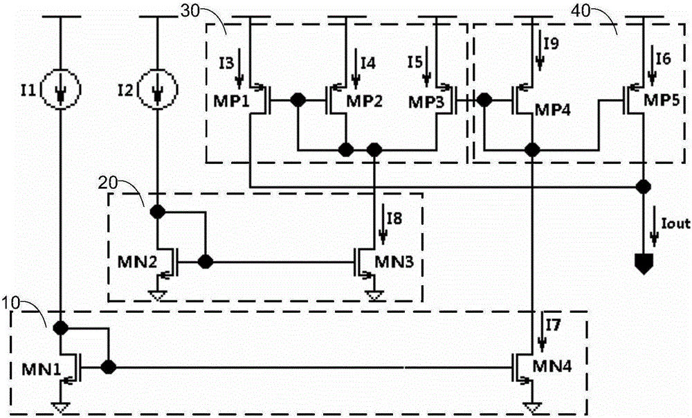
[0035] figure 2 It is a schematic circuit diagram of a current mode circuit for maximum current in the present invention. Such as figure 2 As shown, a current mode circuit for maximum current in the present invention includes: a first current mirror 10 , a second current mirror 20 , an arithmetic unit 30 , and a third current mirror 40 .

[0036] Wherein, the first current mirror 10 is ...


PUM


Abstract

The invention discloses a current mode circuit of a maximum current value. The current mode circuit comprises a first current mirror, a second current mirror, an operation unit and a third current mirror, wherein the first current mirror is used for converting first input current into first current sink; the second current mirror is used for converting second input current into second current sink; the operation unit is used for generating an operation result according to relative sizes of the first current sink and the second current sink; the third current mirror is used for converting the first current sink into current source output; the current source output of the operation unit and the current source output of the third current mirror are summed to be used as final current output; and the current mode circuit of the maximum current value, which is simple in structure, low in power consumption and small in occupied chip area is realized.

Description

technical field [0001] The invention relates to a circuit, in particular to a current mode circuit with the maximum current value. Background technique [0002] Currently, the current maximum circuit is widely used in the field of measurement and control. figure 1 A schematic circuit diagram of a conventional current maximum circuit. Among them, the NMOS transistors MN1 and MN2, the PMOS transistors MP1, MP2 and MP3 constitute the current sink current mirror and the current source current mirror respectively, the NMOS transistor MN3, the PMOS transistor MP4 and MP5 are all used as switches, and the function of the resistor R1 is to flow through it. Current is converted to voltage. [0003] The NMOS transistors MN4 - MN6 , the PMOS transistors MP6 - MP10 and the resistor R2 form a circuit identical to the above to process the input current I2 . [0004] The NMOS transistors MN7 and MN8 form a current sink current mirror, and the PMOS transistors MP11 and MP12 form a curren...

Claims


Application Information

Patent Timeline
Patent Type & Authority Applications(China)
IPC IPC(8): G05F3/26
CPCG05F3/262
Inventor 秦义寿
Owner SHANGHAI HUAHONG GRACE SEMICON MFG CORP
Why Eureka
Try Eureka