
Mapping method for data collected by automatic safety device and EMS system primary equipment model

A safe, automatic, one-time device technology, applied in electrical digital data processing, special data processing applications, design optimization/simulation, etc., can solve problems such as lack of data support, correlation, and inability to read real-time operating data, so as to improve data maintenance The effect of improving efficiency and improving accuracy

Active Publication Date: 2016-12-07
POWER DISPATCHING CONTROL CENT OF GUANGDONG POWER GRID CO LTD
View PDF3 Cites 6 Cited by
  • Summary
  • Abstract
  • Description
  • Claims
  • Application Information

AI Technical Summary

Problems solved by technology

[0007] The above technology can realize the data collection and uploading of relay protection devices and substations, but the real-time operation data collected by the devices and related equipment, such as current, voltage, power, etc., cannot be accurately associated with the EMS model, resulting in During the power system simulation, the simulation software cannot accurately and quickly read the real-time operation data of the primary equipment collected by the safety automatic device from the EMS model, and lacks the data support for simulating the action behavior of the safety automatic device under the expected failure of the power grid

Method used


Image

  • Mapping method for data collected by automatic safety device and EMS system primary equipment model
  • Mapping method for data collected by automatic safety device and EMS system primary equipment model
  • Mapping method for data collected by automatic safety device and EMS system primary equipment model

Examples


Embodiment Construction

[0020] An embodiment of a method for mapping data collected by a safety automatic device and a primary equipment model of an EMS system according to the present invention will be described in detail below in conjunction with the accompanying drawings.

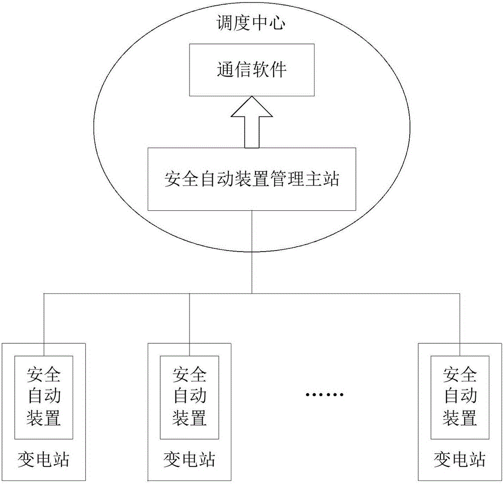
[0021] The mapping method of the data collected by the safety automatic device of the present invention and the primary equipment model of the EMS system is jointly realized by the communication software of the safety automatic device management master station of the dispatching center and a plurality of safety automatic devices, refer to figure 1 as shown, figure 1 It is a schematic diagram of the structure of the safety automatic device management master station and the safety automatic device. A plurality of the safety automatic devices are respectively installed in each substation, and each of the safety automatic devices communicates and interacts with the communication software installed in the safety automatic device man...


PUM


Abstract

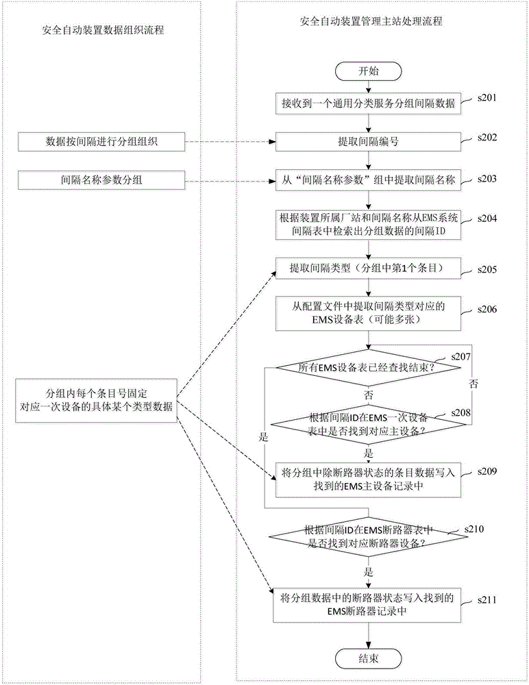
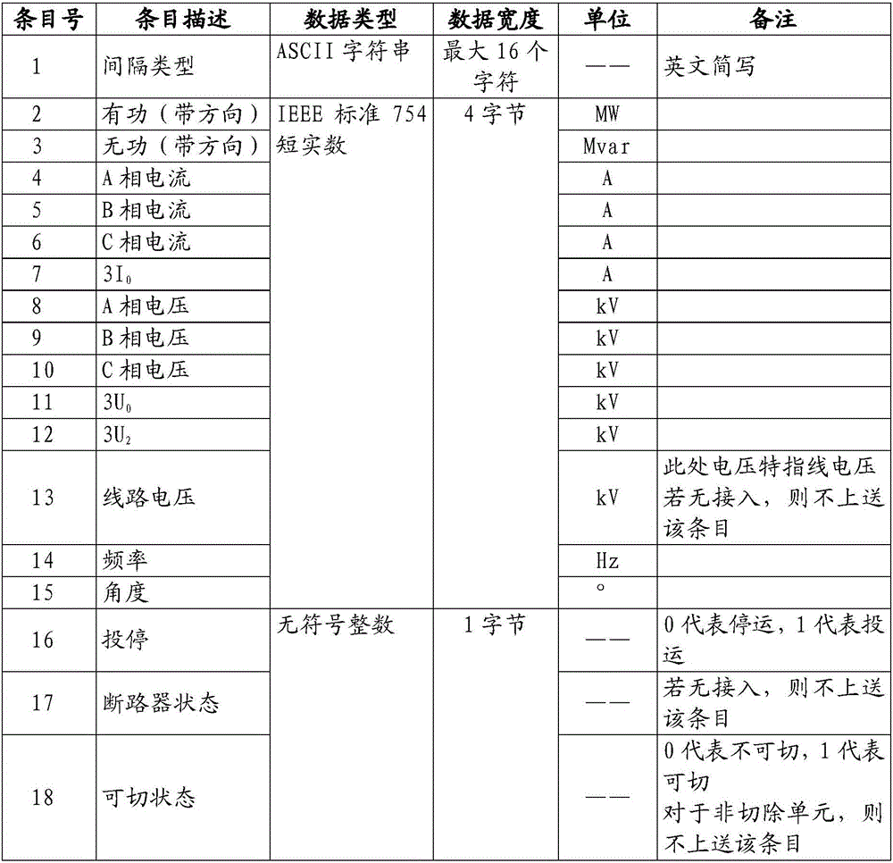
The invention relates to a mapping method for data collected by an automatic safety device and an EMS system primary equipment model. The mapping method comprises the steps that the automatic safety device collects real-time operating data of primary equipment, and grouping organization is carried out in an electrical power system interval mode; the data is placed in a universal classification service group structure to be uploaded to a management master station of the automatic safety device; the management master station receives interval data of universal classification service groups through communication software, and interval serial numbers are extracted from group names; the interval name parameter groups are searched for interval dispatching names corresponding to the interval serial numbers, the EMS module is searched for corresponding interval IDs according to the interval dispatching names in a matching mode, the primary equipment in the EMS model is positioned according to the interval types included in the interval data groups and the interval IDs, and the values of fixed items in the real-time operating data are written in an attribute domain corresponding to the primary equipment in the EMS model. The accuracy of the data corresponding relationship is improved on the premise of improving data maintenance efficiency.

Description

technical field [0001] The invention relates to the technical field of power system scheduling operation monitoring, in particular to a mapping method between data collected by a safety automatic device and a primary equipment model of an EMS system. Background technique [0002] Power system safety automatic devices include safety and stability control devices, low-frequency and low-voltage load shedding devices, out-of-step decoupling devices, and backup power automatic input devices. The configuration ratio is very high. The correctness and effectiveness of the actions of safety automatic devices are related to the safety, stability and reliability of power grid power supply. The operation modes of AC-DC hybrid power grids are diversified. Faced with such a large number of safety automatic devices, the safety automatic device strategy formulated offline is Whether it can operate reasonably under actual complex working conditions, and whether the operation will bring abou...

Claims


Application Information

Patent Timeline
IPC IPC(8): G06F17/50
CPCG06F30/20Y02E60/00
Inventor 魏宏陈兴华吴国炳李力李新超陈锦昌杨文佳陈睿郑丹
Owner POWER DISPATCHING CONTROL CENT OF GUANGDONG POWER GRID CO LTD
Learn More