
an optical module

A technology of optical module and optical path, which is applied in the field of optical communication, can solve the problems of not being able to provide 25Gbps burst reception, unable to provide technical solutions, etc., and achieve the effect of increasing the rate, reducing requirements, and high-speed signal transmission

Active Publication Date: 2019-03-29
HISENSE BROADBAND MULTIMEDIA TECH
View PDF5 Cites 0 Cited by
  • Summary
  • Abstract
  • Description
  • Claims
  • Application Information

AI Technical Summary

Problems solved by technology

[0004] The shortcoming of the existing technology is that, taking the current demand for 25Gbps rate as an example, the existing 100GEthernet technology can be used for reference for the downlink 25Gbps transmission, but on the uplink receiving end, especially during the burst reception, due to the burst reception The strict reception establishment time limit at the end makes it impossible to provide a technical solution for 25Gbps burst reception at present. Obviously, the existing technology cannot provide a technical solution for higher rate burst reception.

Method used


Image

  • an optical module
  • an optical module

Examples


Embodiment Construction

[0017] Specific embodiments of the present invention will be described below in conjunction with the accompanying drawings.

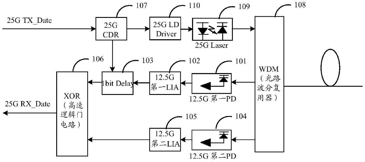
[0018] figure 1 It is a schematic structural diagram of an optical module of an optical line terminal of an access network. As shown in the figure, the optical module may include: a first PD (Photo-electric Detector, photoelectric detector) 101, a Delay (delay circuit) 103, a second PD 104, logic gate 106, wherein:

[0019] a first photodetector, converting the received optical signal of the first wavelength into a first electrical signal, and sending the first electrical signal to the delay circuit;

[0020] a delay circuit, delaying the first electrical signal and inputting it into a logic gate circuit;

[0021] a second photodetector, converting the received optical signal of the second wavelength into a second electrical signal, and inputting the second electrical signal into the logic gate circuit;

[0022] The logic gate circuit combines the se...


PUM


Abstract

The invention discloses an optical module, which includes a first photodetector, a delay circuit, a second photodetector, and a logic gate circuit, wherein: the first photodetector converts the received optical signal of the first wavelength into a first The electrical signal is used to transmit the first electrical signal to the delay circuit; the delay circuit is used to delay the first electrical signal and input it to the logic gate circuit; the second photodetector is used to convert the received optical signal of the second wavelength into a second electrical signal, The second electrical signal is input into the logic gate circuit; the logic gate circuit combines the second electrical signal with the delayed first electrical signal and outputs it. The invention can reduce the requirement on the receiver, realize the doubling of the rate, and solve the problem of the receiving rate of the access network.

Description

technical field [0001] The invention relates to the technical field of optical communication, in particular to an optical module. Background technique [0002] The optical network is the infrastructure of the entire information communication network. The rapid development and application of optoelectronic science and technology research has greatly promoted the development of the information communication industry. The practice of optical communication development at home and abroad has proved that optical communication technology has become an important factor involving national security and enhancing comprehensive national strength, and it is also a key element to gain advantages in the fierce global economic competition. With the continuous growth of user demand for high-bandwidth services such as high-definition IPTV (Internet Protocol Television, interactive network television), video surveillance, etc., the industry has gradually realized that the existing EPON (Ethern...

Claims


Application Information

Patent Timeline
Patent Type & Authority Patents(China)
IPC IPC(8): H04B10/60H04Q11/00
Inventor 张强赵其圣
Owner HISENSE BROADBAND MULTIMEDIA TECH
Learn More