Prefabricated fiber dispersing device and method and application thereof

A fiber dispersion and pre-allocation technology, which is applied in the fields of chemical instruments and methods, earth square drilling, transportation and packaging, etc., can solve the problems of uneven dispersion of fibers, and achieve the effect of facilitating laying, reducing filtration loss and preventing backflow

Active Publication Date: 2016-12-14
BC P INC CHINA NAT PETROLEUM CORP +1
View PDF7 Cites 4 Cited by
  • Summary
  • Abstract
  • Description
  • Claims
  • Application Information

AI Technical Summary

Problems solved by technology

[0004] The purpose of the present invention is to solve the problem that the fibers in the current oil a

Method used


Image

  • Prefabricated fiber dispersing device and method and application thereof

Examples


Embodiment 1

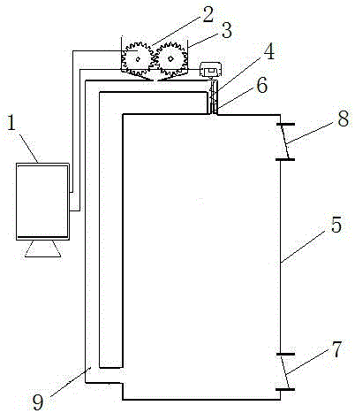
[0021] Aiming at the problem that the current fiber addition method cannot meet the requirement that the fiber is uniformly dispersed in the liquid, this example provides figure 1 A preconfigured fiber dispersing device shown includes a preconfigured tank 5, a liquid inlet 8 and a liquid outlet 7 are opened on the side wall of the preconfigured tank 5, and the liquid inlet 8 is located above the liquid outlet 7. The bottom of the dispensing tank 5 is connected with a circulation manifold 9, and the circulation manifold 9 is connected with a screw pump 4, the outlet end of the screw pump 4 communicates with the top of the pre-dispensing tank 5, and the circulation manifold 9 is equipped with a feed box 3, which feeds The bottom of the material box 3 communicates with the circulation manifold 9, and the gear disperser 2 is installed in the material box 3;

[0022] The gear disperser 2 and the screw pump 4 are all connected to a set of driving devices, and the driving devices are...

Embodiment 2

[0027] On the basis of Embodiment 1, the outlet end of the screw pump 4 is connected with a restrictor 6 .

[0028] This embodiment adopts two-stage dispersion, the fibers enter the gear disperser 2 for one-stage dispersion, the liquid mixed with fibers is sucked and pressurized by the screw pump 4, and a high-pressure zone is formed at the restrictor 6, when the mixture of high-pressure liquid and fibers flows out When restrictor 6, because the reason of pressure reduction takes place dispersion expansion, bundle fiber is dispersed into silk fiber and enters in the pre-allocation tank 5, and this is two-stage dispersion.

[0029] The liquid enters the pre-allocation tank 5 through the liquid inlet 8, the liquid in the pre-allocation tank 5 flows into the circulation manifold 9, the liquid inlet 8 and the liquid outlet 7 are closed, and the fiber is added from the opening at the top of the feed box 10, After the fibers are dispersed by the gear disperser 2, they enter the circ...

Embodiment 3

[0032] It should be noted that the gear disperser 2 is composed of two meshing gears. In order to facilitate the rapid falling of the fibers under the action of gravity, the feed box 10 is in the shape of a funnel. The driving device includes a motor and a coupling, the motor is connected to two gears or screw pumps through the coupling, and the motor is connected to the controller 1 . The added fiber length is 8mm, and in order to bend the fiber from different angles, the gear shaft length is 40cm.


PUM


Abstract

The invention provides a prefabricated fiber dispersing device and method and application thereof. Two-stage dispersion is adopted, fibers are firstly put into a gear disperser composed of two engaged gears for first-stage dispersion, liquid mixed with the fibers is pressurized through a screw pump, a high-pressure area is formed on a throttling device, finally the mixture is injected into a prefabricating tank, second-stage dispersion is achieved, the fibers are expanded and dispersed from the high-pressure area to a low-pressure area, and liquid in which the fibers are evenly dispersed is formed. The whole process is controlled through a controller in real time, and the number of circulating times can be adjusted according to the dispersion degree of the fibers. The need of evenly dispersing the fibers in the liquid can be met through the two stages of dispersion, the sand carrying capacity of the liquid can be improved through the evenly dispersed fibers, the laying degree of a propping agent in a crack can be promoted, the friction of the liquid is reduced, leak off of the liquid in the stratum is reduced, and backflow of the propping agent is prevented.

Description

technical field [0001] The invention belongs to the technical field of petroleum exploitation, and in particular relates to a preconfigured fiber dispersion device, method and application. Background technique [0002] Adding fiber in the fracturing process of oil and gas field development is beneficial to improve the sand-carrying capacity of the liquid, the degree of proppant laying in the fracture, reduce the friction of the liquid, reduce the fluid loss of the liquid in the formation, and prevent the backflow of the proppant . However, during on-site construction, the uneven dispersion of fibers often causes damage to the pump plug of the fracturing vehicle and blockage of the wellbore. In the past, fibers were mainly added manually or by wind pressure dispersion. However, these methods cannot directly and evenly disperse the fibers in the liquid, and require a sand mixer to mix in advance or add additional devices for separate mixing, which cannot meet the needs of on-...

Claims


Application Information

Patent Timeline
IPC IPC(8): B01F13/10B01F5/18B01F5/10E21B43/267B01F25/70
CPCE21B43/267B01F25/53B01F25/70B01F33/82B01F2101/50
Inventor 陈飞孙虎张冕池晓明周真袁海平姬随波马新东柴龙刘欢袁伟文陶长州许洪星贾凯雄陈建林
Owner BC P INC CHINA NAT PETROLEUM CORP
Why Eureka
Try Eureka