Intelligent detecting and sizing device for aeroengine spindle

An aero-engine and intelligent detection technology, which is applied in the direction of measuring devices, optical devices, instruments, etc., can solve the problems of reducing the accuracy of workpieces, high labor intensity, and affecting performance, so as to eliminate errors caused by human participation, reduce labor intensity, and improve The effect of production efficiency

Active Publication Date: 2016-12-14
XI AN JIAOTONG UNIV
View PDF7 Cites 3 Cited by
  • Summary
  • Abstract
  • Description
  • Claims
  • Application Information

AI Technical Summary

Problems solved by technology

After the shaft parts are processed and heat-treated, a certain amount of residual stress is often generated inside the part, and with the release of the residual stress, the part will inevitably produce residual strain or even bending deformation. These defects reduce the accuracy of the workpiece and seriously affect its performance
In mechanical processing, the inner hole processing is mainly done by drilling, boring and milling, etc. The accuracy of the through hole with a short length can be guaranteed, but the machining accuracy cannot be guaranteed for a longer through hole. The length of the inner hole of the hollow aeroengine spindle is close 2 meters, and the ratio of depth to diameter is nearly 90. The current processing technology is difficult to meet its requirements
[0003] At present, the shaping industry of shaft parts is often determined by the operator based on experience to determine the pressing force and shaping force. The labor intensity is high, the production efficiency is low, the shaping accuracy is low, and the quality is unstable, which cannot meet the needs of industrial development.

Method used


Image

  • Intelligent detecting and sizing device for aeroengine spindle
  • Intelligent detecting and sizing device for aeroengine spindle
  • Intelligent detecting and sizing device for aeroengine spindle

Examples


Embodiment Construction

[0022] The present invention will be described in detail below in conjunction with the accompanying drawings and embodiments.

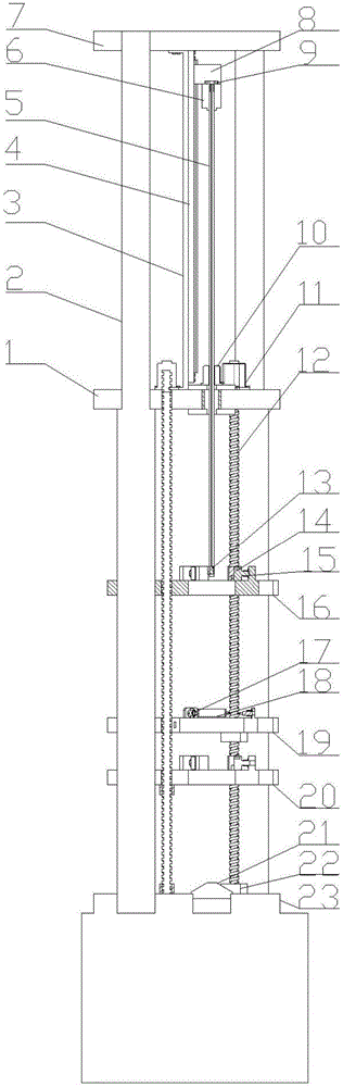
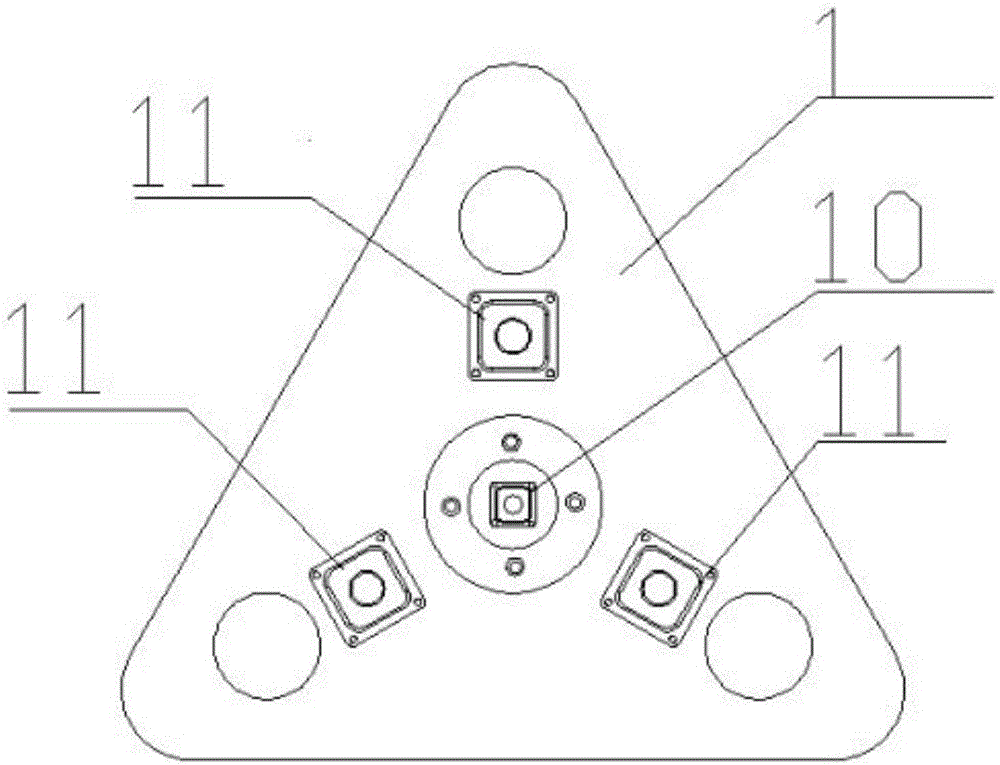
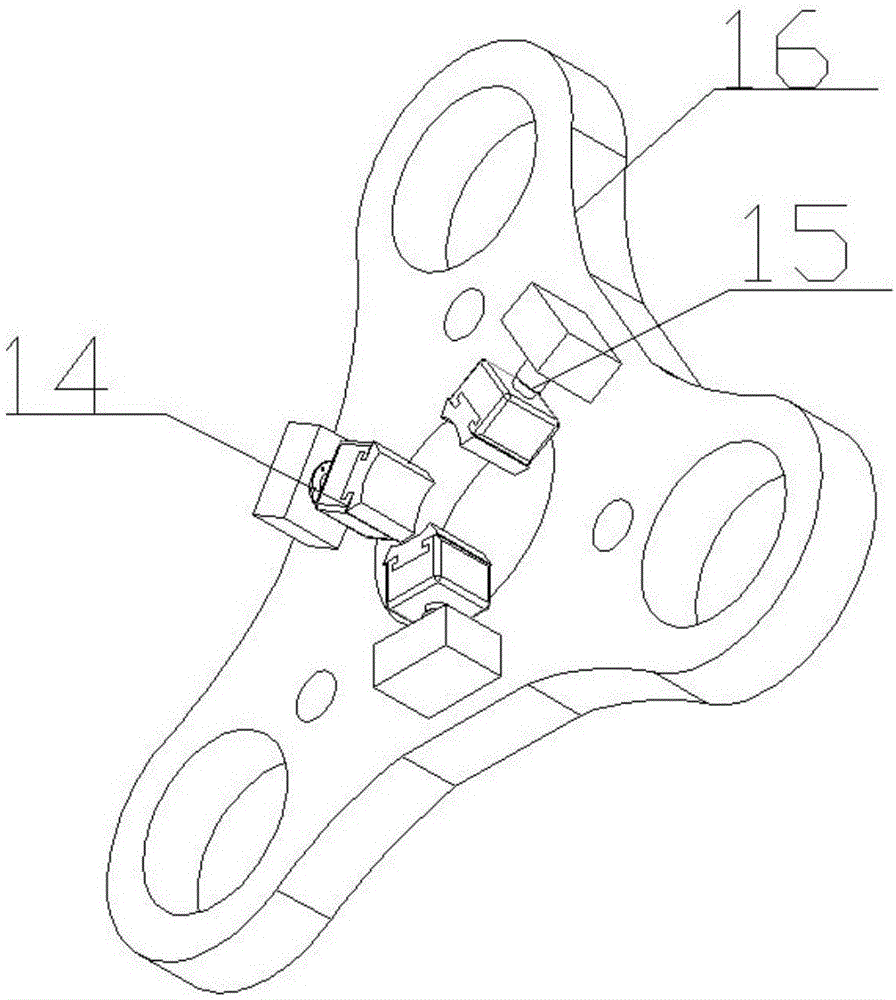
[0023] refer to figure 1 , figure 2 , image 3 and Figure 4 , an intelligent detection and correction device for an aero-engine main shaft, comprising a base 23, the base 23 is connected to the lower ends of three columns 2 that are evenly distributed around the circumference, and the middle and upper parts of the columns 2 are respectively connected with a lower fixing plate 1 and an upper fixing plate 7. , the lower part of the column 2 is sequentially connected with a lower clamping plate 20, a shape-correcting plate 19, and an upper clamping plate 16 from bottom to top;

[0024] A grating ruler guide rail 4 is fixed between the upper fixing plate 7 and the lower fixing plate 12, the grating ruler 3 connected on the grating ruler guide rail 4 is provided with a grating ruler displacement sensor slider 8 on the grating ruler guide rail 4, and t...


PUM


Abstract

The invention provides an intelligent detecting and sizing device for an aeroengine spindle. The intelligent detecting and sizing device comprises a base; the base is connected with three upright columns which are uniformly distributed in a circumferential manner; the upright columns are connected with a lower clamping plate, a sizing plate, an upper clamping plate, a lower fixing plate and an upper fixing plate; a grating ruler guide rail and a grating ruler are fixed between the upper fixing plate and the lower fixing plate; a grating ruler displacement sensor sliding block is connected with a probing screw rod which is connected with an optical fiber displacement sensor probe; a screw rod stepping motor which forms a screw rod pair with the probing screw rod is installed in the center of lower clamping plate; three stepping motors are uniformly distributed at the periphery of the screw rod stepping motor and are connected with the upper ends of three lead screws respectively; the lead screws form lead screw pairs with the upper clamping plate, the sizing plate and the lower clamping plate respectively and are fixed to the base; three hydraulic cylinders are uniformly distributed on each of the upper and lower clamping plates along the circumference; a piston rod of each hydraulic cylinder is fixed with a clamping head; three hydraulic cylinders are uniformly distributed at the periphery of the sizing plate along the circumference; and the end part of each piston rod of each hydraulic cylinder is connected with a sizing ring through a flexible steel wire rope. With adoption of the intelligent detecting and sizing device, stable intelligent detection and sizing with high accuracy and high efficiency is realized.

Description

technical field [0001] The invention relates to the technical field of intelligent shape correction, in particular to an intelligent detection and shape correction device for an aero-engine main shaft. Background technique [0002] The main shaft of the aero-engine is an important part that connects the compressor and turbine components and transmits power, and is a key part of the aircraft engine. Aeroengine spindles require very high machining accuracy and reliability. After the shaft parts are processed and heat-treated, a certain amount of residual stress is often generated inside the part, and with the release of the residual stress, the part will inevitably produce residual strain or even bending deformation. These defects reduce the accuracy of the workpiece and seriously affect its performance. In mechanical processing, the inner hole processing is mainly done by drilling, boring and milling, etc. The accuracy of the through hole with a short length can be guarante...

Claims


Application Information

Patent Timeline
Patent Type & Authority Applications(China)
IPC IPC(8): B21D3/00G01B11/00
CPCG01B11/00B21D3/00
Inventor 张琦李文浩马小伟梁正龙王聚存章灿保文成
Owner XI AN JIAOTONG UNIV
Why Eureka
Try Eureka