Mechanical expanding machine for large-diameter ring piece

A large-diameter, diameter-expanding machine technology, applied in the field of diameter-expanding machines, can solve the problems of overall size and volume, material waste, energy loss and energy waste, and achieve the effects of convenient use, material saving and maintenance cost reduction

Active Publication Date: 2016-12-14
CENT SOUTH UNIV
View PDF14 Cites 24 Cited by
  • Summary
  • Abstract
  • Description
  • Claims
  • Application Information

AI Technical Summary

Problems solved by technology

With the rapid development of aerospace and heavy-duty industries, the main load-bearing components are developing in the direction of large-scale integration, and the diameter of connecting ring components has also expanded from 3 to 5 meters to 8 to 10 meters. For ring parts, if the traditional expansion head is still used when expanding the diameter, since the inclined block, wedge-shaped body and fan-shaped mold of the expanded head are all solid bodies, the overall size of the wedge-shaped body, inclined block and fan-shaped mold of the expanding machine is the same as The volume will be very large, which will not only cause waste of materials, but also cause energy loss and energy waste due to the need to push the giant inclined block and fan-shaped mold to run

Method used


Image

  • Mechanical expanding machine for large-diameter ring piece
  • Mechanical expanding machine for large-diameter ring piece
  • Mechanical expanding machine for large-diameter ring piece

Examples


Embodiment Construction

[0027] The present invention will be further described below in conjunction with the accompanying drawings.

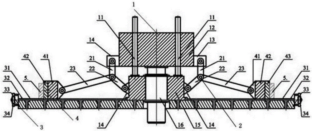
[0028] Such as figure 1 As shown, the large-diameter ring mechanical expansion machine provided by the present invention includes a hydraulic drive device 1, a hinge rod booster device 2, a support disc structure 3 and a split punch 4, and the support disc 33 is fixed on the ground On the upper surface, a fixed worktable 15 is arranged at the center of the upper surface. The piston cylinder 16 is installed in the center hole of the fixed worktable 15 and connected with the lower end surface of the slider 12 through the piston rod. The lower ends of four guide columns 11 evenly distributed along the circumference are fixed. On the fixed worktable, the cylinder part fits with the four guide sleeves inside the slider 12, and the upper and lower chambers of the piston cylinder 16 are connected with hydraulic oil circuits (not shown in the figure). Under the action of not ...


PUM

PropertyMeasurementUnit
diameteraaaaaaaaaa

Abstract

The invention discloses a mechanical expanding machine for a large-diameter ring piece. The mechanical expanding machine for the large-diameter ring piece comprises a piston cylinder, a supporting disk, a fixed workbench and a sliding block. The fixed workbench is arranged at the center of the upper surface of the supporting disk. The piston cylinder is installed in the fixed workbench and is connected with the lower end face of the fixed workbench through a piston rod. At least two hinged rod force amplifying devices are evenly arranged in the circumferential direction of the fixed workbench. Sectioned male dies corresponding to the hinged rod force amplifying devices are evenly distributed on the supporting disk in the circumferential direction of the fixed workbench. The bottom of each sectioned male die is provided with a guide groove, and each sectioned male die slides in a radial guide rail on the supporting disk under the action of the corresponding hinged rod force amplifying device. According to the mechanical expanding machine for the large-diameter ring piece, a hinged rod force amplifying mechanism is adopted, force exerted by the hydraulic cylinder on the sliding block is amplified, and therefore the mechanical expanding machine can obtain large output force. The mechanical expanding machine for the large-diameter ring piece is particularly suitable for expanding of the large-diameter ring piece with the diameter larger than 5 m. In addition, the hinged rod force amplifying mechanism is convenient to use and maintain, accessories of the hinged rod force amplifying mechanism are convenient to replace, and the production and manufacturing cost of the hinged rod force amplifying mechanism is low.

Description

technical field [0001] The invention relates to a diameter enlarging machine, in particular to a mechanical enlarging machine for large-diameter rings. Background technique [0002] Mechanical expansion is an advanced manufacturing technology and an important process link in the manufacture of large-diameter, high-grade pipeline steel pipes and large connecting rings for aerospace weapons and equipment. Mechanical diameter expansion generally adopts the principle of oblique block hole expansion, and the ring is plastically deformed by the segmented punch to improve the size and shape accuracy of the product, eliminate the welding residual stress, and at the same time form a residual stress state that is conducive to improving the bearing capacity of the product. , and the purpose of increasing the yield strength. [0003] The expanding head of the mechanical expanding machine is composed of fan-shaped mold, inclined block and wedge-shaped body. The sector mold is fixed on ...

Claims


Application Information

Patent Timeline
Patent Type & Authority Applications(China)
IPC IPC(8): B21D41/02B21D37/10B21D37/12
CPCB21D37/10B21D37/12B21D41/028
Inventor 李毅波黄明辉潘晴
Owner CENT SOUTH UNIV
Why Eureka
Try Eureka