Device for avoiding excessive punching of punching machine

A punching machine and punching head technology, which is applied in the field of devices to avoid excessive punching of punching machines, can solve problems such as damage to punching parts, difficulty in controlling the movement stroke of punching head, etc., and achieve the effect of preventing damage.

Active Publication Date: 2016-12-14
CHONGQING ZETIAN AUTO PARTS
View PDF5 Cites 2 Cited by
  • Summary
  • Abstract
  • Description
  • Claims
  • Application Information

AI Technical Summary

Problems solved by technology

[0004] The purpose of the present invention is to provide a device for avoiding excessive stamping of the stamping machine, so as to solve the problem tha...

Method used


Image

  • Device for avoiding excessive punching of punching machine
  • Device for avoiding excessive punching of punching machine

Examples


Embodiment Construction

[0013] The present invention will be described in further detail below by means of specific embodiments:

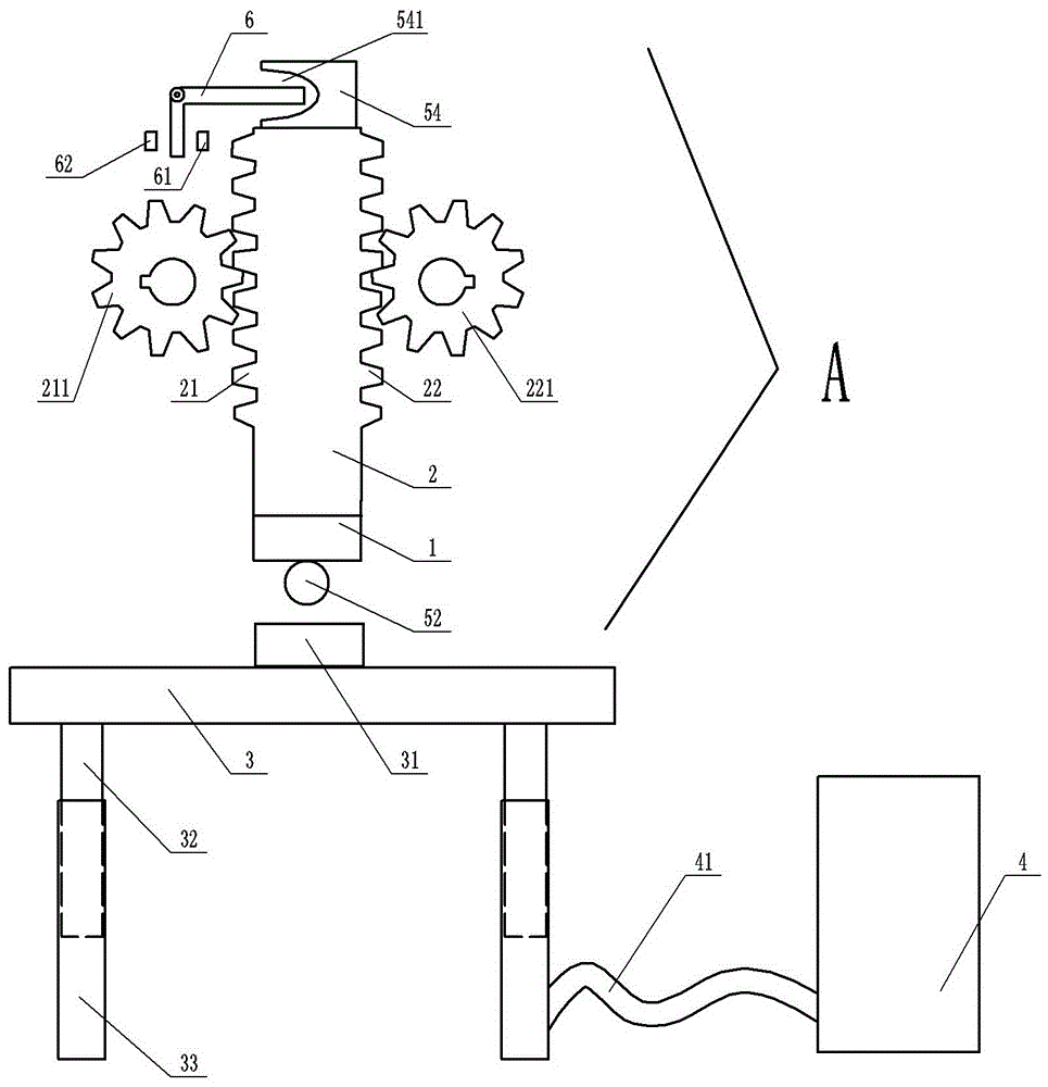
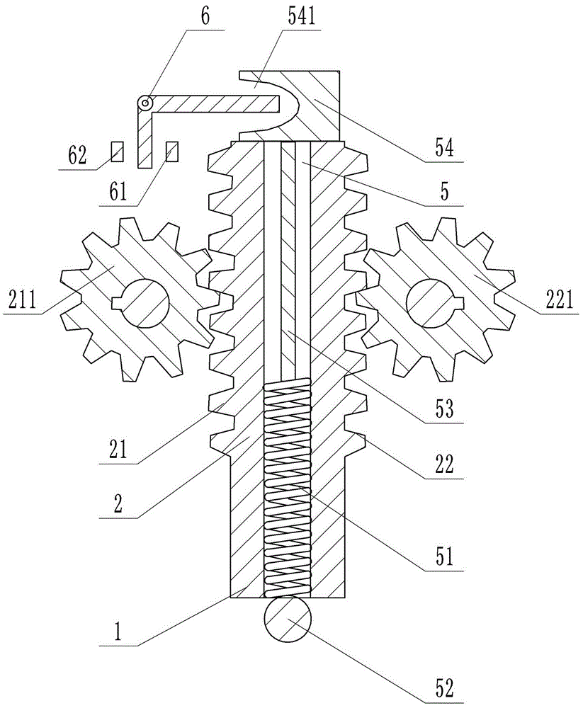
[0014] The reference signs in the accompanying drawings of the description include: stamping head 1, support seat 2, first rack 21, second rack 22, driving gear 211, reset gear 221, base 3, punching chamber 31, movable plunger 32, Fixed column 33, hydraulic station 4, high pressure pipe 41, through hole 5, spring 51, starting ball 52, connecting rod 53, driving block 54, arc groove 541, L-shaped bar 6, start switch 61, stop switch 62.

[0015] like figure 1 , figure 2 As shown, the present invention includes a base 3, a control system, a power system, and a punching system. The upper end surface of the base 3 is provided with a punching chamber 31, and the workpiece to be punched can be placed on the punching chamber 31. The lower end surface of the base 3 is provided with two movable plungers 32, and the bottom of the movable plungers 32 is connected with the fixed co...


PUM


Abstract

The invention belongs to the technical field of punching machining, and specifically discloses a device for avoiding excessive punching of a punching machine. The device comprises a base, a control system, a power system and a punching system. The control system comprises a spring, a connection rod, a drive block, a support, a start switch and a stop switch. The lower end of the spring is connected with a start ball. The upper end of the spring is connected with the connection rod. The drive block is arranged on the head portion of the connection rod. An arc-shaped groove is formed in one side of the drive block. An L-shaped rod capable of rotating relatively is connected to the support and comprises a long rod and a short rod. The long rod is located in the arc-shaped groove. The start switch is located on the side, close to the drive block, of the short rod. The stop switch is located on the other side of the short rod. By means of contact of the short rod and the start switch or the stop switch, movement or stop of a punch is achieved. Due to the adoption of the technical scheme, the defect that the movement stroke of a punch of a punching machine in the prior art is difficult to control can be overcome.

Description

technical field [0001] The invention belongs to the technical field of stamping processing, and in particular relates to a device for avoiding excessive stamping of a stamping machine. Background technique [0002] Punching machine is a kind of mechanical equipment that drives the flywheel through the motor, and drives the crank linkage mechanism through the clutch and the transmission gear to move the slider up and down, and drives the punching head to form the stamping parts. However, in the stamping process of the existing stamping machine, because the movement stroke of the stamping head of the stamping machine sometimes needs to be controlled manually, it is not easy to control the stamping position of the stamping head by human control, so that it may be over-stamped, causing a certain degree of damage to the stamped parts. damage. [0003] In view of the above reasons, it is necessary to improve the existing stamping machine to solve the above problems. Contents of...

Claims


Application Information

Patent Timeline
IPC IPC(8): B30B15/14B30B15/28
CPCB30B15/14B30B15/28
Inventor 黄忠泽
Owner CHONGQING ZETIAN AUTO PARTS
Why Eureka
Try Eureka