Front-end buffer device for streetcar

A technology for trams and buffer devices, applied in the direction of railway vehicle wheel guards/buffers, transportation and packaging, railway car body parts, etc., which can solve the problem of large installation space, long travel of energy-absorbing components, and installation of energy-absorbing devices The seat size and other problems can be improved to achieve the effect of improving the absorption capacity and high maintainability

Inactive Publication Date: 2016-12-14
CRRC NANJING PUZHEN CO LTD
View PDF6 Cites 11 Cited by
  • Summary
  • Abstract
  • Description
  • Claims
  • Application Information

AI Technical Summary

Problems solved by technology

[0003] The disadvantage of this structure is that the stroke of the energy-absorbing element is long, and it needs to occupy a large installation space in the direction of the vehicle length, and the diameter of the energy-absorbing element is relatively large, and the mounting seat of the energy-absorbing device is relatively large, which causes the impact of the entire buffer device on the height direction. When the folding coupler is unfolded, when the vehicle needs to be connected and operated, the buffer device needs to be lifted to complete the unfolding of the folding coupler and the connecting of the vehicle
At this time, although the vehicle can be connected normally, the vehicle has lost the collision protection function.
Therefore, a compact buffer device structure is needed to solve the problems of lack of installation space and the inability of vehicles to be directly connected

Method used


Image

  • Front-end buffer device for streetcar
  • Front-end buffer device for streetcar

Examples


Embodiment Construction

[0017] The preferred technical solutions of the present invention will be described in detail below in conjunction with the accompanying drawings.

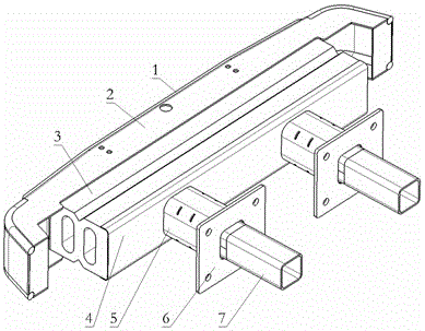
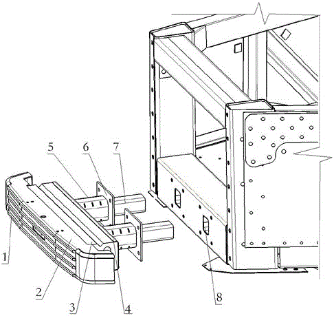
[0018] Such as figure 1 As shown, a kind of front-end buffer device for tram of the present invention comprises anti-climbing teeth 1, connecting plate 2, rubber buffer 3, energy-absorbing tube 5, mounting seat 6 and square guide bar 7, and described connecting plate 2. Located between the anti-climbing gear 1 and the rubber buffer 3, a square guide rod 7 is arranged through the rubber buffer 3. One end of the square guide rod 7 is connected to the connecting plate 2, and the other end is inserted into the Front end, also be provided with on the square guide bar 7 and be used to be fixed on the mounting seat 6 of the front end of tram, between described mounting seat 6 and rubber buffer 3, there is energy-absorbing tube 5, has induction hole on the energy-absorbing tube 5, can The pressure feed force for the initial deformation o...


PUM


Abstract

The invention discloses a front-end buffer device for a streetcar. The front-end buffer device for the streetcar comprises an anti-crawling tooth, a connecting plate, a rubber buffer device, energy absorption pipes, installation seats and square guide rods; the connecting plate is located between the anti-crawling tooth and the rubber buffer device; the square guide rods penetrate through the rubber buffer device; one end of each square guide rod is connected with the connecting plate, and the other end of each square guide rod is inserted into the front end of the streetcar; the energy absorption pipes are arranged between the installation seats and the rubber buffer device; and the square guide rods are sleeved with the energy absorption pipes correspondingly. Compared with the prior art, the front-end buffer device for the streetcar has an elastic energy absorption buffer function and a plastic deformation buffer function, and has a second-stage of energy absorption effect; in low-speed crush, only the rubber buffer device transforms elastically, and no other parts are damaged, that is, no other parts need replacing; and in high-speed crush, the rubber buffer device transforms first, plastic deformation of the energy absorption pipes occurs and energy is absorbed when the rubber buffer device can not continue transforming, the energy absorption capability of a vehicle in crush is effectively improved.

Description

technical field [0001] The invention relates to a collision energy absorbing and buffering structure, in particular to a front-end buffering device for a tram, belonging to the field of rail transit vehicle structure design. Background technique [0002] Trams are road vehicles. According to the EN 15227 standard, the collision performance of trams must meet the requirements of the same train for frontal collision and side collision with obstacles. Therefore, an energy-absorbing buffer device must be installed at the front end of the train. At present, the buffer device used in the tram is composed of a C-shaped anti-collision beam at the front and two energy-absorbing elements at the rear. The anti-collision beam and the energy-absorbing element are connected to the car body chassis through fasteners. [0003] The disadvantage of this structure is that the stroke of the energy-absorbing element is long, and it needs to occupy a large installation space in the direction of t...

Claims


Application Information

Patent Timeline
Patent Type & Authority Applications(China)
IPC IPC(8): B61F19/04
CPCB61F19/04
Inventor 鲍伟兵邓锐黄鹏王兴文叶佳周春艳张丽
Owner CRRC NANJING PUZHEN CO LTD
Why Eureka
Try Eureka