Supercharge Your Innovation With Domain-Expert AI Agents!

Tilt-rotor unmanned aerial vehicle

A tilt-rotor and unmanned aerial vehicle technology, applied in the field of unmanned aerial vehicles, can solve problems such as aircraft crashes, insufficient reliability and maintainability of aircraft, complex mathematical modeling and control problems of tilt-rotor aircraft, and achieve simplified and complex structures The effect of high degree, improved reliability and compact structure

Inactive Publication Date: 2016-12-14
SHAANXI WODE AEROSPACE TECH CO LTD +1
View PDF5 Cites 1 Cited by
  • Summary
  • Abstract
  • Description
  • Claims
  • Application Information

AI Technical Summary

Problems solved by technology

Due to the unique design of the tilt-rotor aircraft in terms of power plant and structural layout, especially the influence of its power tilt angular velocity on the stability and control characteristics of the aircraft, it is significantly different from traditional aircraft. Therefore, the tilt-rotor The mathematical modeling and control problems of aircraft are much more complicated than traditional aircraft
The current theoretical research, especially the research on the dynamic process of power tilting, is still not perfect, which leads to the obvious lack of reliability and maintainability of the current tilt-rotor aircraft, and the design method of flight safety needs to be improved
[0004] In the working mode of the scheme of using two independent engines to work at the same time, it is very likely that the entire aircraft will crash due to an engine accident at one end

Method used


Image

  • Tilt-rotor unmanned aerial vehicle
  • Tilt-rotor unmanned aerial vehicle
  • Tilt-rotor unmanned aerial vehicle

Examples


Embodiment Construction

[0041] The technical solution of the present invention will be further described in detail below in conjunction with the accompanying drawings and specific embodiments.

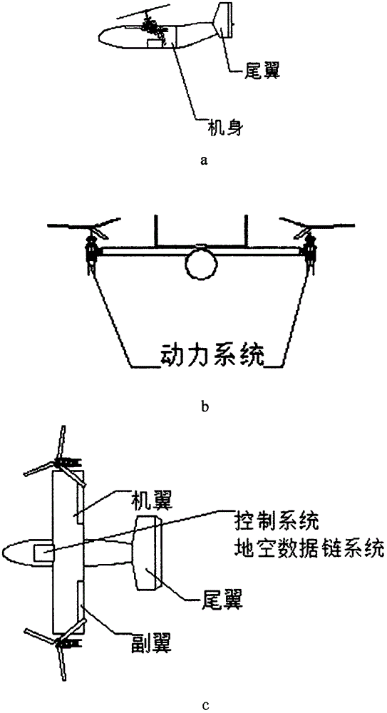
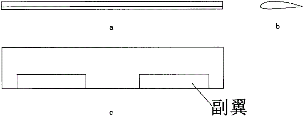
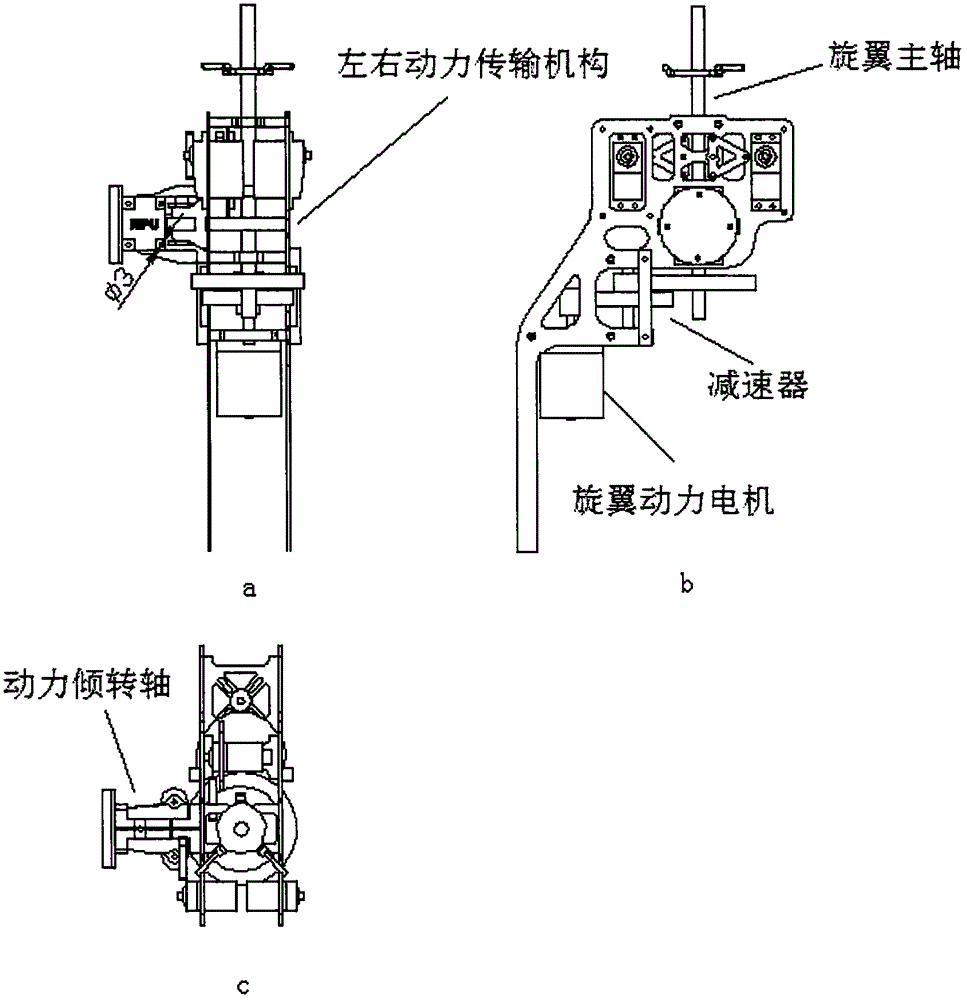
[0042] like Figure 1 to Figure 6 As shown, a tilting rotor UAV includes wings, ailerons, empennage, fuselage, power system, control system, ground-air data link system, and the power system includes a power tilting mechanism, a motor and a propeller, The middle part of the wing is designed and installed with pinch pulleys and free-steering guide rings. The fuselage adopts the form of load-bearing bulkheads and full skin. The frames are connected and positioned by carbon tubes. The middle section of the fuselage is equipped with landing gear installation partitions and equipment compartment floors, which are connected with the middle section of the fuselage with tenons and tenons. The upper edge of the fuselage is opened with platform grooves. The wing beams are connected with screws, and the upper edge of t...


PUM


Abstract

The invention discloses a tilt-rotor unmanned aerial vehicle. The tilt-rotor unmanned aerial vehicle comprises a wing, ailerons, an empennage, a fuselage, a power system, a control system and a ground-air data chain system; the power system comprises a power tilting mechanism, a motor and an airscrew; a pinch roller and a free-turning guide ring are arranged on the middle of the wing; the fuselage adopts the forms of load bearing bulkheads and a full skin; the bulkheads are connected and positioned through carbon tubes; the middle section of the fuselage is a circular cross section and contracts into a guide circle forward and backward; the middle section of the fuselage is provided with an undercarriage installation baffle and an equipment compartment floor which are connected with the bulkheads of the middle section of the fuselage through tenons and mortises; a platform groove is formed in the upper edge of the middle of the fuselage; a carbon tube beam groove made from a laminate on a platform is connected with a wing beam though screws; and a platform groove is formed in the upper edge of the tail part of the fuselage and is connected with a horizontal tail through screws. The tilt-rotor unmanned aerial vehicle is compact in structure, improves reliability and is suitable for application and popularization.

Description

technical field [0001] The present invention relates to an unmanned aerial vehicle, in particular to a tilting rotor unmanned aerial vehicle. Background technique [0002] The tilt-rotor aircraft combines the features of fixed-wing aircraft and helicopters, and is vividly called the "hybrid" in the air. It has the functions of vertical take-off and landing of helicopters, hovering, front, rear and side flight, and high-speed cruise of fixed-wing aircraft. The characteristics of long range, showing extremely superior maneuverability, has a wide range of application prospects in military and civilian fields, and also lays a technical foundation for the future development of aircraft in the direction of intelligent aerial robots and dexterous aircraft. Marked by the U.S. V-22 "Osprey" aircraft entering service, the research on multi-mode aircraft has made a breakthrough, and initially played an important role in actual combat. [0003] A tilt-wing aircraft acts like a transver...

Claims


Application Information

Patent Timeline
Patent Type & Authority Applications(China)
IPC IPC(8): B64C27/28B64C27/52B64C27/12B64C29/02
CPCB64C27/12B64C27/28B64C27/52B64C29/02B64U10/25B64U10/10
Inventor 郭庆李陶郭英南袁昌盛
Owner SHAANXI WODE AEROSPACE TECH CO LTD
Features
  • R&D
  • Intellectual Property
  • Life Sciences
  • Materials
  • Tech Scout
  • Unparalleled Data Quality
  • Higher Quality Content
  • 60% Fewer Hallucinations
Learn More