Paint storage bucket

A technology for storing barrels and paints, applied in the field of storage barrels, can solve the problems of inconvenient use, single function, poor practicability, etc., and achieve the effects of avoiding chemical changes, good storage effect, and convenient entry and exit.

Inactive Publication Date: 2016-12-14
哈尔滨漆艺之星科技发展有限公司
View PDF0 Cites 1 Cited by
  • Summary
  • Abstract
  • Description
  • Claims
  • Application Information

AI Technical Summary

Problems solved by technology

[0003] The purpose of the present invention is to provide a paint storage bucket, which solves the problems of single function, poor practicability, and inconvenient use of paint storage equipment in the prior art. The present invention realizes vacuum storage of paint, and has a stirring function, which can Store the paint better, effectively avoid a series of chemical changes caused by the contact of the paint with the air, improve the storage effect of the paint, and ensure the quality of the paint storage

Method used


Image

  • Paint storage bucket

Examples


Embodiment 1

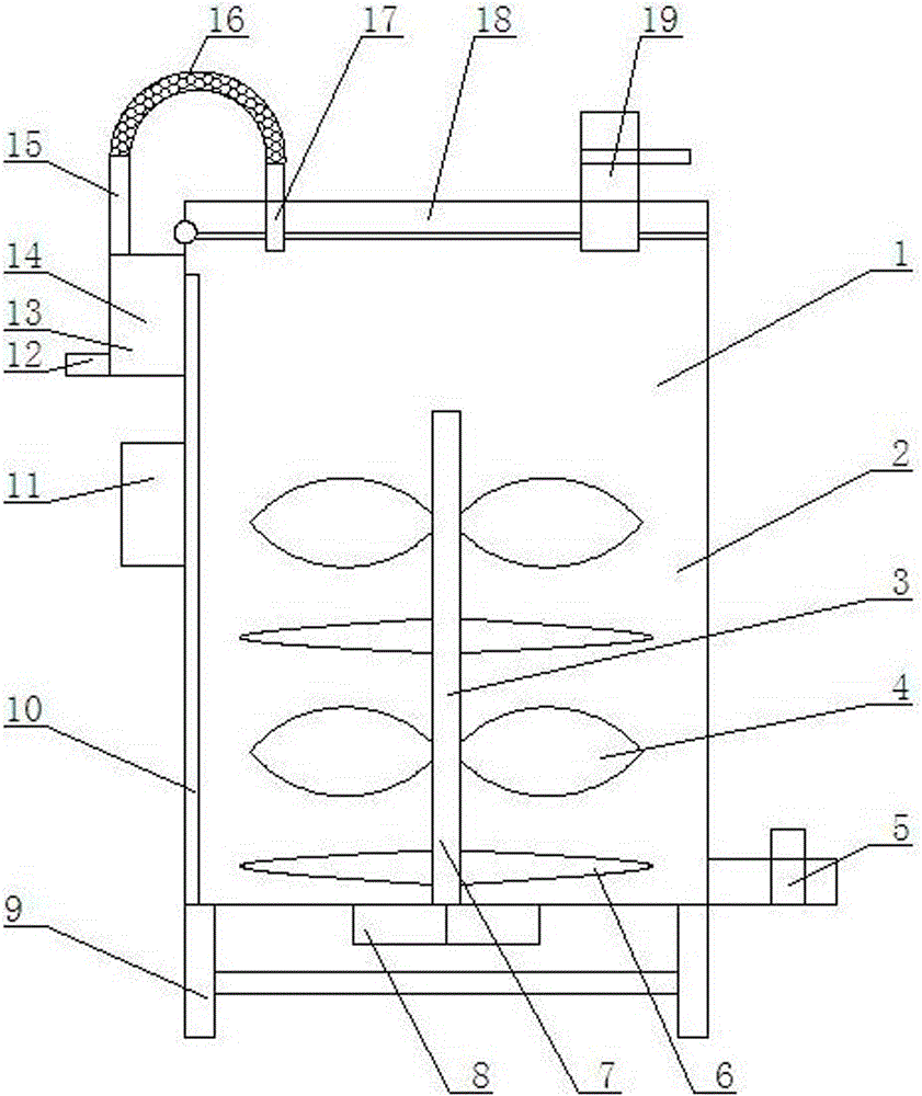
[0015] Such as figure 1 Shown, a kind of paint storage barrel, comprises barrel body 1, support frame 9, vacuum device 13, stirring device 3, and described barrel body 1 bottom is supported by support frame 9; Described barrel body 1 is supported by barrel cover 18 1. The bucket body 2 is composed of the lower left end of the bucket cover 18 connected to the upper left end of the bucket body 2 by a flip connector; The paint discharge pipe 5 is installed at the lower right end; the vacuum device 13 is installed at the upper left side of the barrel body 2, and the middle end device controller 11 is installed at the left side; the stirring device 3 is installed at the lower end of the barrel body 2, and the left end of the barrel body 2 Install the paint liquid level device 10; the controller 11 is connected to control the vacuum device 13, the stirring device 3, and the paint liquid level device 10.

Embodiment 2

[0017] Such as figure 1 As shown, the vacuum device 13 is composed of a vacuum device 14, a vacuum pipe 15, a telescopic flexible connecting pipe 16, an air suction pipe 17, and an exhaust pipe 12; , the upper end of the vacuum pump 14 is connected to the vacuum tube 15, the vacuum tube 15 is connected to the telescopic flexible connecting tube 16, the other end of the telescopic flexible connecting tube 16 is connected to the suction tube 17, and the other end of the suction tube 17 passes through the barrel cover 18 and is inserted into the barrel Inside the body 1; the exhaust pipe 12 is installed at the left end of the vacuum pump 14.

Embodiment 3

[0019] Such as figure 1 Shown, each device a control valve on described paint feed pipe 19 and paint discharge pipe 5.


PUM


Abstract

The invention provides a paint storage bucket. The paint storage bucket comprises a bucket body, a supporting frame, a vacuumizing device and a stirring device. The bottom end of the bucket body is supported by the supporting frame. The bucket body is composed of a bucket cover and a bucket body part. The left-lower end of the bucket cover is connected with the left-upper end of the bucket body part through a turning connection piece. A paint inlet pipe inserted into the bucket body is arranged at the upper end of the right side of the bucket cover. A paint outlet pipe is arranged at the right-lower end of the bucket body part. The vacuumizing device is arranged at the upper end of the left side of the bucket body part, and a controller is arranged in the middle of the left side of the bucket body part. The stirring device is arranged at the lower end of the interior of the bucket body part. A paint liquid level unit is arranged at the left end of the interior of the bucket body. The controller is connected with the vacuumizing device, the stirring device and the paint liquid level unit in a controlling mode. By the adoption of the paint storage bucket, the problems that in the prior art, paint storage equipment is simplex in function, poor in practicability and inconvenient to use are solved; and vacuum storage of paint is achieved, a stirring function is achieved, the paint can be well stored, the situation that the paint makes contact with air, and consequentially a series of chemical changes of the paint are caused is effectively avoided, and the paint storage effect is improved.

Description

technical field [0001] The invention relates to a storage barrel, in particular to a paint storage barrel. Background technique [0002] Paint is one of the main raw materials for making lacquer paintings. If the paint is placed in the air for a long time, it will solidify or change color. The solidified paint will gradually harden, and the solidified paint is very inconvenient to brush. , and affect the brushing effect, and improper storage of the paint will cause a series of chemical changes in the paint, which will affect the subsequent use of the paint. Therefore, the storage of paint is very important. At present, most of the existing paint storage containers only have a simple storage function, single function, poor practicability, and poor storage effect. There is also the problem of very inconvenient paint production, which is inconvenient to use and affects the production efficiency of lacquer paintings. Contents of the invention [0003] The purpose of the pres...

Claims


Application Information

Patent Timeline
Patent Type & Authority Applications(China)
IPC IPC(8): B65D81/20B01F7/16B01F13/06
CPCB65D81/2038B01F27/074B01F27/112B01F27/171B01F27/192B01F27/80B01F27/90B01F33/70B01F2101/30
Inventor 白艳萍
Owner 哈尔滨漆艺之星科技发展有限公司
Why Eureka
Try Eureka