A control method for an optimal operation control system of a low-temperature economizer
A low-temperature economizer and control system technology, applied in the direction of controlling feed water, feed water heaters, lighting and heating equipment, etc., can solve the problem of installing flow measurement devices, unable to understand the water side flow of low-temperature economizers, and the thermal power of low-temperature economizers Economical and other issues, to achieve the effect of maximizing energy saving benefits
- Summary
- Abstract
- Description
- Claims
- Application Information
AI Technical Summary
Problems solved by technology
Method used
Image
Examples
Embodiment 1
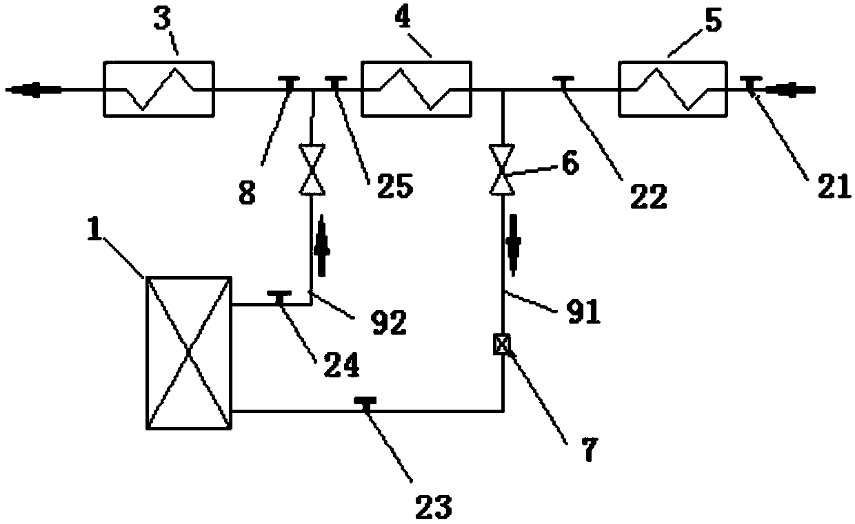
[0040] A low-temperature economizer 1 optimal operation control system, including a low-temperature economizer 1, a water-side inlet pipeline 91 and a water-side outlet pipeline 92, and the low-temperature economizer 1 passes through the water-side inlet pipeline 91 The connecting pipeline 92 on the water side is connected across the two ends of the recuperation heater 4, and the control valve 6 is installed on the water-side connecting pipeline 91 at the inflow end of the low-temperature economizer 1, which is characterized in that: A condensate flowmeter 7 is also provided on the pipeline 91, and the condensate flowmeter 7 is installed on the downstream side of the control valve 6, and a No. Temperature instrument 22, the No. 2 temperature instrument 22 is set on the upstream side of the inlet of the water side access pipeline 91, and No. 3 temperature instrument 23 is installed on the downstream side of the condensate flow meter 7, and the pipeline is connected to the water ...
Embodiment 2
[0045] The present invention also provides a control method for the optimal operation control system of the above-mentioned low-temperature economizer 1, which is characterized in that the steps are as follows:
[0046] Step 1. Adjust the opening of the control valve 6 to 20% through the DCS control system, and calculate the heat absorption Q of the low-temperature economizer 1 under the current state DW-1 , record the flow q of the condensate flowmeter 7 in the current state 1 ;
[0047] Q DW-1 =q 1 (h 1 smq -h 1 j+1 )
[0048] where h 1 smq is the current outlet water enthalpy value of low-temperature economizer 1, and is the temperature obtained by No. 4 temperature meter 23 in the current state and the acquired pressure P of the pressure gauge 8 1 , obtained by using the water vapor function formula, h 1 j+1 is the current inlet water enthalpy value of low-temperature economizer 1, and is the temperature obtained by No. 3 temperature instrument 24 in the curr...
PUM
 Abstract
Description
Claims
Application Information
 - R&D
- Intellectual Property
- Life Sciences
- Materials
- Tech Scout
- Unparalleled Data Quality
- Higher Quality Content
- 60% Fewer Hallucinations
Browse by: Latest US Patents, China's latest patents, Technical Efficacy Thesaurus, Application Domain, Technology Topic, Popular Technical Reports.
© 2025 PatSnap. All rights reserved.Legal|Privacy policy|Modern Slavery Act Transparency Statement|Sitemap|About US| Contact US: help@patsnap.com


