Classified combustion chamber adopting multi-point injection combustion stabilization classes for improving combustion stability

A technology of combustion chamber and stable combustion stage, which is applied in the direction of liquid fuel burners, burners, burners, etc., and can solve the problems of main combustion stage flame stability, combustion chamber main combustion stage flameout, main combustion stage large air flow, etc. Achieve excellent ignition performance and improve combustion stability

Active Publication Date: 2016-12-14
INST OF ENGINEERING THERMOPHYSICS - CHINESE ACAD OF SCI
View PDF6 Cites 2 Cited by
  • Summary
  • Abstract
  • Description
  • Claims
  • Application Information

AI Technical Summary

Problems solved by technology

[0005] The technical problem to be solved by the present invention is: the air flow rate of the main combustion stage at the head of the graded combustion chamber is relatively large, and the ignition energy generated by the igniter is difficult to penetrate the airflow of the main combustion stage to ignite the pre-combusti

Method used


Image

  • Classified combustion chamber adopting multi-point injection combustion stabilization classes for improving combustion stability
  • Classified combustion chamber adopting multi-point injection combustion stabilization classes for improving combustion stability
  • Classified combustion chamber adopting multi-point injection combustion stabilization classes for improving combustion stability

Examples


Embodiment Construction

[0036] In order to make the object, technical solution and advantages of the present invention clearer, the present invention will be further described in detail below with reference to the accompanying drawings and examples. It should be noted that the following descriptions are only preferred embodiments of the present invention, and therefore do not limit the protection scope of the present invention.

[0037] It should be noted that implementations not shown or described in the accompanying drawings are forms known to those of ordinary skill in the art. In addition, the directional terms mentioned in the following embodiments, such as "upper", "lower", "front", "backward", "left", "right", "top", "bottom", etc., are only for reference The orientation of the graph. Accordingly, the directional terms are used to illustrate and not to limit the invention.

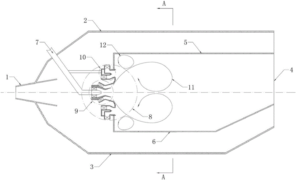
[0038] Such as figure 1 As shown, it is the basic structure diagram of the staged combustion chamber that adopts the ...


PUM


Abstract

The invention relates to a classified combustion chamber adopting multi-point injection combustion stabilization classes for improving combustion stability. A structure of an oil gas mixing device at the head portion of the classified combustion chamber comprises center combustion stabilization class assemblies, periphery combustion stabilization class assemblies and main combustion class assemblies. The center combustion stabilization class assemblies are located in the centers of the main combustion class assemblies, and every two periphery combustion stabilization class assemblies are located between the corresponding two adjacent main combustion class assemblies. When ignition is conducted in the combustion chamber, an igniter firstly ignites the periphery combustion stabilization class assemblies close to an outer ring of a flame tube and then ignites the other periphery combustion stabilization class assemblies and the center combustion stabilization class assemblies. Due to the fact that energy of the igniter does not need to penetrate main combustion class air stream, the ignition performance of the classified combustion chamber is greatly improved; and when the combustion chamber works in a large-power state, the center combustion stabilization class assemblies, the periphery combustion stabilization class assemblies and the main combustion class assemblies supply oil at the same time, the center combustion stabilization class assemblies and the periphery combustion stabilization class assemblies have a stabilizing function on main combustion class flames at the same time, and the stability of large-power-state main combustion class combustion is improved.

Description

technical field [0001] The invention is applied to the field of aero-engine combustors, and in particular relates to civil low-pollution combustors and military high-temperature rise combustors using staged combustion technology. Background technique [0002] At present, there are two main application directions for staged combustors. One is a low-pollution combustor, which is mainly used in civil aero engines, with high combustion efficiency and low pollutant emissions (mainly nitrogen oxides and carbon monoxide) as its main technical features. , and its typical representatives are the TAPS combustor applied to the GEnx engine and the TAPS II combustor applied to the GE9x engine. The TAPS and TAPS II combustors adopt the concept of staged and partitioned combustion. Most of the fuel and air are mixed through the main combustion stage to achieve premixed and partially premixed combustion, thereby reducing the temperature of the main combustion zone and thermal nitrogen oxide...

Claims


Application Information

Patent Timeline
IPC IPC(8): F23D11/24F23D11/40F23D11/38
CPCF23D11/24F23D11/383F23D11/40F23D11/406F23D2202/00F23D2209/20
Inventor 杨金虎刘富强刘存喜穆勇徐纲
Owner INST OF ENGINEERING THERMOPHYSICS - CHINESE ACAD OF SCI
Why Eureka
Try Eureka