
Three-dimensional pulsating heat pipe heat radiation and cooling device with flat plate microchannel evaporator

A pulsating heat pipe, heat dissipation and cooling technology, which is applied in the cooling/heating device, lighting device, cooling/ventilation/heating renovation of lighting devices, etc. Safety and reliability reduction and other issues, to achieve the effect of no maintenance production cost, strong cooling and temperature control effect, and enhanced reliability

Inactive Publication Date: 2016-12-14
江苏中圣压力容器装备制造有限公司
View PDF6 Cites 1 Cited by
  • Summary
  • Abstract
  • Description
  • Claims
  • Application Information

AI Technical Summary

Problems solved by technology

However, the forced convection cooling of the microchannel in this device requires an external power unit or auxiliary equipment, which increases the complexity and cost of the system, and relies heavily on external coolant and power supply, which reduces its safety and reliability. Restricted its popularization and application

Method used


Image

  • Three-dimensional pulsating heat pipe heat radiation and cooling device with flat plate microchannel evaporator
  • Three-dimensional pulsating heat pipe heat radiation and cooling device with flat plate microchannel evaporator
  • Three-dimensional pulsating heat pipe heat radiation and cooling device with flat plate microchannel evaporator

Examples


Embodiment Construction

[0024] The present invention will be described in further detail below in conjunction with specific embodiments and drawings, but the embodiments of the present invention are not limited thereto.

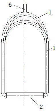
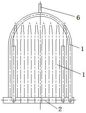
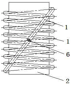
[0025] An embodiment of the three-dimensional pulsating heat pipe cooling device with flat plate microchannel evaporator of the present invention is as follows Figure 1 to Figure 3 As shown, it includes a metal plate evaporator 2 with a microchannel array inside and a capillary tube. The bottom surface of the metal plate evaporator 2 is used to connect with high-power microelectronic devices or LED lamps. The microchannel 3 in the metal plate evaporator 2 It is arranged between the upper surface and the bottom surface of the metal plate evaporator 2, and the ports of each microchannel 3 are respectively arranged on the left and right sides of the metal plate evaporator 2, and the capillary 1 is connected with the microchannel 3. The capillary 1 in this embodiment adopts Copper capi...


PUM

PropertyMeasurementUnit
Diameteraaaaaaaaaa

Abstract

The invention discloses a three-dimensional pulsating heat pipe heat radiation and cooling device with a flat plate microchannel evaporator. The three-dimensional pulsating heat pipe heat radiation and cooling device comprises the metal plate evaporator and capillary pipes, wherein a microchannel array is arranged in the metal plate evaporator. The bottom face of the metal plate evaporator is used for being connected with a high-power microelectronic device or an LED lamp. Microchannels in the metal plate evaporator are arranged between the upper surface and the bottom face of the metal plate evaporator. End openings of the microchannels are formed in the left side and the right side of the metal plate evaporator. The left end of one capillary pipe is in sealed connection with the end opening of the microchannel at the rearmost end of the left side of the metal plate evaporator, and the other end of the capillary pipe is in sealed connection with the end opening of the microchannel at the headmost end of the right side of the metal plate evaporator. The left ends of the rest of the capillary pipes are in sealed connection with the end openings of the previous microchannels on the left side of the metal plate evaporator, and the other ends of the rest of the capillary pipes are in sealed connection with the end openings of the next microchannels on the right side of the metal plate evaporator. The capillary pipes communicate with the microchannels to form a three-dimensional space loop structure. Cooling working media are injected in the microchannels and the capillary pipes.

Description

technical field [0001] The invention relates to the technical field of heat dissipation and cooling of high-power microelectronic devices or LED lamps, in particular to a three-dimensional pulsating heat pipe heat dissipation and cooling device with a flat plate microchannel evaporator. Background technique [0002] In recent years, with the rapid development of microelectronics technology, various information and communication products are being highly integrated and miniaturized at an unprecedented speed, which directly leads to a significant increase in their working heat load and heat generation per unit area. The negative impact of components is great, and the problem of heat dissipation is becoming more and more prominent, and has become an important bottleneck restricting its development. The heat dissipation problem also affects high-power LED lamps based on lighting purposes. If the heat dissipation conditions of high-power LED lamps cannot be improved in time to re...

Claims


Application Information

Patent Timeline
IPC IPC(8): F28D15/04H05K7/20F21V29/51
CPCF28D15/04F21V29/51H05K7/20336
Inventor 郭宏新屈健刘丰李奇孙田李晖
Owner 江苏中圣压力容器装备制造有限公司
Learn More