Low-impulse efficient pressure-resistant oil gas cooler

An oil-air cooler, high-efficiency technology, applied in the direction of indirect heat exchangers, heat exchanger shells, heat exchanger sealing devices, etc., can solve the problems of oil-air coolers that cannot be installed normally, limit the application of oil-air coolers, and have large volumes of oil-air coolers To prevent leakage, reduce the risk of leakage, and increase reliability

Inactive Publication Date: 2016-12-14
WUXI FANGSHENG HEAT EXCHANGER MFG
View PDF5 Cites 0 Cited by
  • Summary
  • Abstract
  • Description
  • Claims
  • Application Information

AI Technical Summary

Problems solved by technology

Oil cooler is a kind of oil cooling equipment commonly used in hydraulic system and lubrication system. Using this equipment, two fluid media with a certain temperature difference can realize heat exchange, so as to reduce the temperature and ensure the normal operation of the system. Oil cooling Coolers are widely used in various industries such as plastic machinery, construction machinery, mining machinery, automobiles, steel, wind power, aerospace, etc.; however, the oil-gas coolers in the prior art are usually large in size, and in some cases, due to the limitation of the installation area , the oil-air cooler with a conventional structure cannot be installed normally, and its cooler efficiency will be affected, thus limiting the application of the oil-air cooler

Method used


Image

  • Low-impulse efficient pressure-resistant oil gas cooler
  • Low-impulse efficient pressure-resistant oil gas cooler
  • Low-impulse efficient pressure-resistant oil gas cooler

Examples


Embodiment Construction

[0015] The specific embodiments of the present invention will be described below in conjunction with the drawings.

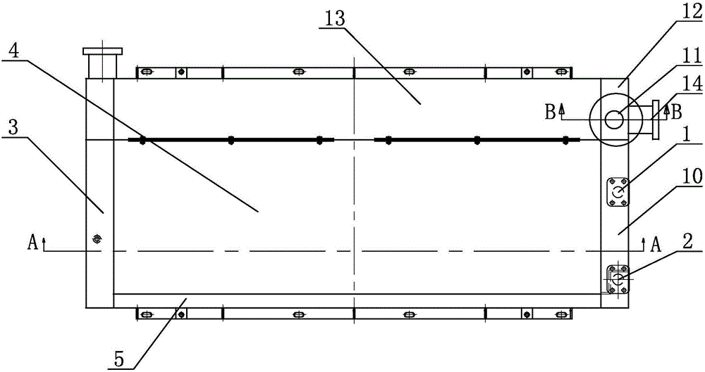
[0016] Such as Figure 1 to Figure 3 As shown, the present invention includes a core body 4, the two ends of the core body 4 are respectively welded with a left head 3 and a right head 10, the oil and gas inlet 1 and the oil and gas outlet 2 are both located on the right head 10, in the right head 10. , The oil and gas inlet 1 and the oil and gas outlet 2 are closed by a partition plate to avoid the communication between the oil and gas inlets and outlets; a bypass pipe 5 is installed on the side wall of the core 4, and the left head 3 communicates with the oil and gas outlet 2 through the bypass pipe 5, and the oil The oil and gas inlet 1 enters and flows back from the oil and gas outlet 2 through the bypass pipe 5 to form a one-way circuit, which solves the problem of inability to install and use because the access is on different sides in actual use; the core 4 ...


PUM


Abstract

The invention relates to a low-impulse efficient pressure-resistant oil gas cooler. The low-impulse efficient pressure-resistant oil gas cooler comprises a core body, a left sealing end and a right sealing end are welded to the two ends of the core body respectively, and an oil gas inlet and an oil gas outlet are located in the right sealing end and are sealed by partition plates in the right sealing end; a by-pass pipe is installed on a side wall of the core body, and the left sealing end communicates with the oil gas outlet through the by-pass pipe; the core body is connected to a second core body through a bolt, first sealing ends are connected to the two ends of the second core body, damping components are installed on medium inlets of the first sealing ends, connectors at the lower ends of the damping components are connected to through connection holes in the first sealing ends in a sealed and clamped mode, and air chambers at the upper parts of the damping components communicate with the through connection holes in the first sealing ends through cavities in the lower parts of the damping components; and flexible films are arranged on sealing layers between the cavities and the air chambers, and flow guide plates are installed at the parts, located in medium channels, of the first sealing ends. The low-impulse efficient pressure-resistant oil gas cooler has the advantages that the structure is simple, installation is convenient, the effect is good, high pressure can be resisted, and the impulse is low.

Description

Technical field [0001] The invention relates to the technical field of coolers, in particular to a novel oil-gas cooler with high efficiency that is convenient for installation. Background technique [0002] A cooler is a type of heat exchange equipment, which is a device used to cool fluid or gas. Under normal circumstances, water or air is used as a coolant to remove heat; coolers are divided into partition coolers, spray coolers, jacket coolers and coil coolers, etc. Coolers are widely used in induction furnaces, intermediate frequency Furnace and other large electrical equipment are matched with pure water, water air, oil water, oil air cooling devices as cooling protection auxiliary equipment; among them, the gas cooler is a cooler used to cool high-temperature gas, and the hot gas in the tube passes through the tube wall and fins It exchanges heat with the cold medium outside the tube, thereby reducing the temperature of the hot gas. Oil cooler is a kind of oil cooling eq...

Claims


Application Information

Patent Timeline
IPC IPC(8): F28D21/00F28F11/00F28F9/26
CPCF28D21/00F28F9/26F28F9/268F28F11/00F28F2225/06
Inventor 张卫锋徐伟斌丁振红丁丽海吴亚红
Owner WUXI FANGSHENG HEAT EXCHANGER MFG
Why Eureka
Try Eureka