A smoke wire flow display control device

A technology of flow display and control device, applied in measurement devices, aerodynamic tests, instruments, etc., can solve the problems of easy burnout, high working voltage of metal wires, unsatisfactory effect, etc., to achieve clear settings and improve success rate. Effect

Inactive Publication Date: 2018-07-06
DALIAN UNIV OF TECH
View PDF8 Cites 0 Cited by
  • Summary
  • Abstract
  • Description
  • Claims
  • Application Information

AI Technical Summary

Problems solved by technology

But it doesn't work well in experiments with slightly higher speeds
There are two main reasons: one is that when the speed is high, the working voltage required by the metal wire is higher, and if the power-on time is slightly deviated, it is easy to burn out; the other is that when the flow speed is high, the delay accuracy is higher, which is used for camera trigger The delay circuit based on variable resistor adjustment is not easy to debug accurately

Method used


Image

  • A smoke wire flow display control device
  • A smoke wire flow display control device

Examples


Embodiment Construction

[0030] The specific implementation manners of the present invention will be further described below in conjunction with the accompanying drawings and technical solutions.

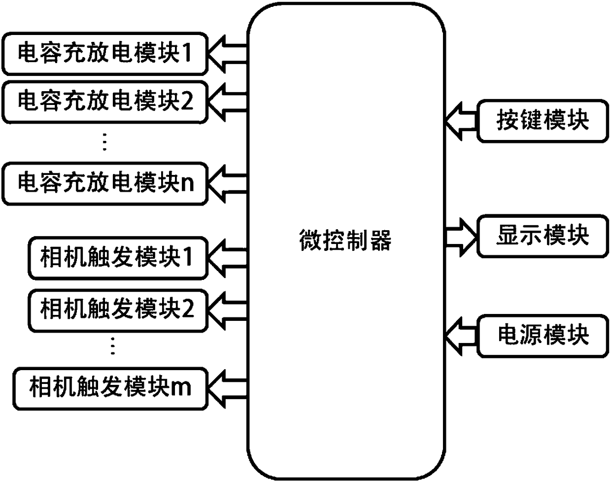
[0031] figure 1 It is a module schematic diagram of a smoke line flow display control device. In the figure, the smoke line flow display control device includes a power supply module, a button module, a display module, a capacitor charging and discharging module and a camera trigger module.

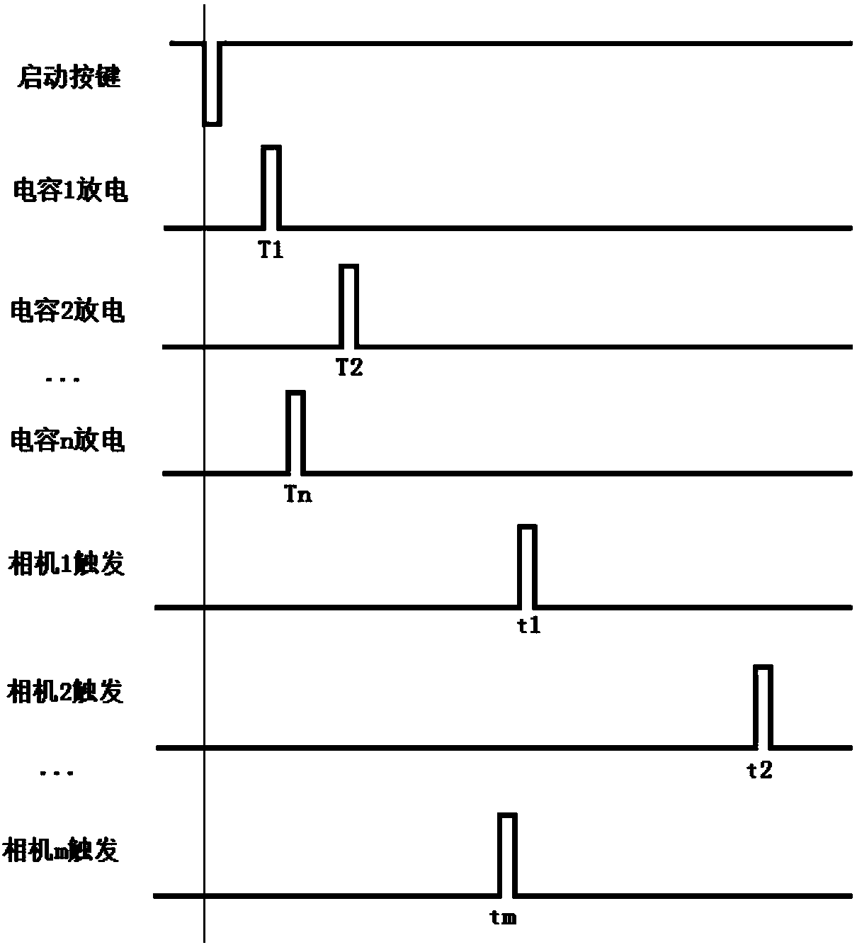
[0032] The working process is as follows:

[0033] After the device is powered on, first use the parameter addition and subtraction, parameter selection and confirmation buttons on the button module to set the voltage of the capacitor charging and discharging module, the discharging time of the charging and discharging module and the triggering time of the camera.

[0034] Press the charging button on the button module, and the device will charge the capacitor charging and discharging module to the set voltage at this...


PUM


Abstract

The invention provides a smoke line flowing display control device for shooting streamline photos in an airflow field, and belongs to the field of flowing display technology. The device comprises a power module, a microprocessor, a capacitor charging and discharging module, a camera trigger module, a key module and a display module; the device can set capacitor charging voltage to discharge a metal wire, and can set the discharging time and the camera trigger time to obtain ideal flowing display photos. In generation of smoke shreds, the metal wire is discharged by using a capacitor charged to certain voltage, and because the energy is fixed, the metal wire is unlikely to damage while lampblack is generated. Smoke can also be produced at a high flowing speed, so that the speed range of smoke line flowing display experiments is enlarged. Ideal photos can be obtained at the speed of less than 18m / s by using the device in practice, the device is greatly improved over the previous experimental device adopting a traditional circuit, and after optimal shooting parameters are determined, the success rate of shooting ideal photos reaches 100%.

Description

technical field [0001] The invention relates to a smoke line flow display control device, which is used for taking pictures of streamlines in an air flow field. Background technique [0002] Smokeline is a direct injection technique for visualization of 2D streamlines of a gas flow field in a wind tunnel. Its implementation is to fix a thin metal wire upstream of the flow field to be observed, and then apply oil to the metal wire so that the oil droplets are evenly distributed on the metal wire. The metal wire is heated by electricity, and the oil droplets are heated to produce oily smoke and form filamentous smoke in the flow field. The smoke is distributed along with the streamline to achieve the purpose of visualizing the streamline in the plane where the shredded tobacco is located. Specific embodiments can refer to the article Jansen Jr B J. Flow visualization through the use of the smoke-wire technique [C] / / AIAA, Aerospace Sciences Meeting.1981,1. [0003] By illumin...

Claims


Application Information

Patent Timeline
Patent Type & Authority Patents(China)
IPC IPC(8): G01M9/06
CPCG01M9/067
Inventor 高南刘玄鹤
Owner DALIAN UNIV OF TECH
Why Eureka
Try Eureka