Power factor corrector and fault diagnosis method and device of current detection circuit of power factor corrector

A power factor correction and current detection circuit technology, which is applied in the direction of measuring devices, electronic circuit testing, instruments, etc., can solve problems such as current deviation, power factor correction control failure, and complex PFC current detection, so as to achieve easy implementation and fault diagnosis Effect

Active Publication Date: 2016-12-14
GD MIDEA AIR-CONDITIONING EQUIP CO LTD +1
View PDF12 Cites 9 Cited by
  • Summary
  • Abstract
  • Description
  • Claims
  • Application Information

AI Technical Summary

Problems solved by technology

The PFC current detection is more complicated, it needs to pass through the current sampling resistor, then pass through the signal conditioning circuit (collectively referred to as the current detection circuit), and then connect to the analog-to-digital conversio

Method used


Image

  • Power factor corrector and fault diagnosis method and device of current detection circuit of power factor corrector
  • Power factor corrector and fault diagnosis method and device of current detection circuit of power factor corrector
  • Power factor corrector and fault diagnosis method and device of current detection circuit of power factor corrector

Examples


Embodiment Construction

[0026] Embodiments of the present invention are described in detail below, examples of which are shown in the drawings, wherein the same or similar reference numerals designate the same or similar elements or elements having the same or similar functions throughout. The embodiments described below by referring to the figures are exemplary and are intended to explain the present invention and should not be construed as limiting the present invention.

[0027] The fault diagnosis method and device of the power factor corrector and its current detection circuit according to the embodiments of the present invention will be described below with reference to the accompanying drawings.

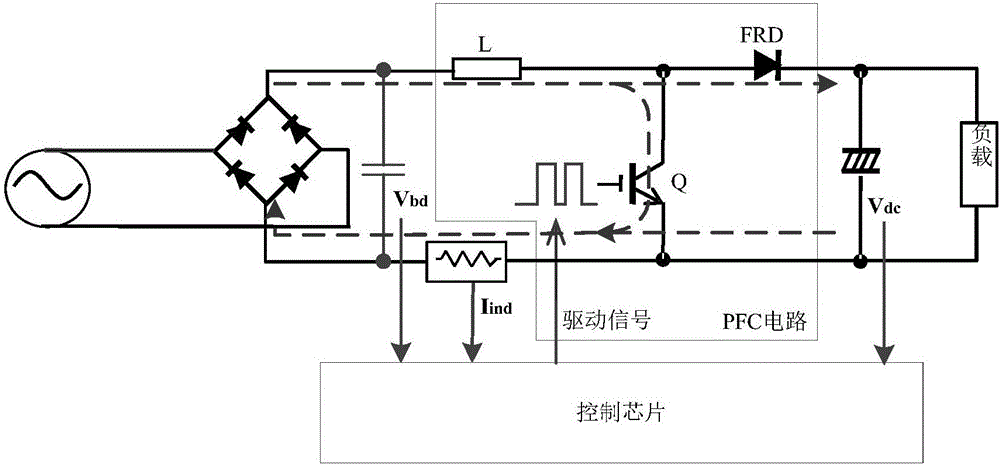
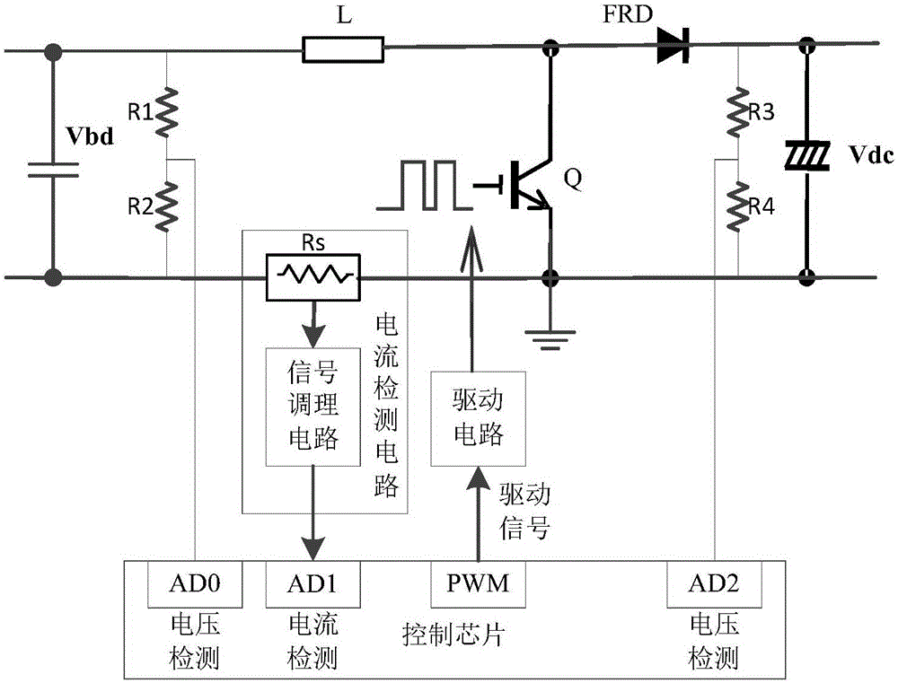
[0028] In the embodiment of the present invention, such as figure 1 As shown, the power factor corrector for single-phase AC input includes a control chip, a main circuit and a detection circuit. The factor corrector includes an inductor, a power switch tube and a diode, wherein the inductor can be ...


PUM


Abstract

The present invention discloses a power factor corrector and a fault diagnosis method and device of a current detection circuit of the power factor corrector. The power factor corrector comprises an inductor, a power switching tube and a diode, and the current detection circuit comprises a sampling resistor and a signal conditioning circuit. The method comprises the following steps of obtaining an input current of the power factor corrector via the current detection circuit when the fault diagnosis is carried out on the current detection circuit; calculating the change rate of the input current of the power factor corrector according to the input current; determining whether the sampling resistor and the signal conditioning circuit go wrong according to the input current and the change rate of the input current. According to the method, by determining the input current obtained by the current detection circuit and the change rate of the input current, the fault diagnosis of the current detection circuit can be realized, and the method is simple and reliable, and is easy to realize.

Description

technical field [0001] The invention relates to the technical field of power factor correction, in particular to a fault diagnosis method and device for a power factor corrector and a current detection circuit thereof. Background technique [0002] Most household appliances adopt the following circuit topology: the single-phase AC power supply outputs a pulsating DC voltage through uncontrollable rectification, and then adjusts the output of a stable DC voltage through a power factor corrector, then connects it to a large-capacity electrolytic capacitor, and finally supplies the internal switching power supply and supply the main load. Among them, the power factor corrector commonly used Boost-type PFC (Power Factor Correction, power factor correction) circuit, which is mainly composed of inductors, power switch tubes and diodes, by detecting the DC voltage at the input side of the PFC circuit, the DC voltage at the output side of the PFC circuit and the PFC current Perform...

Claims


Application Information

Patent Timeline
IPC IPC(8): G01R31/28G01R35/00
CPCG01R31/2825G01R35/00
Inventor 黄招彬张国柱
Owner GD MIDEA AIR-CONDITIONING EQUIP CO LTD
Why Eureka
Try Eureka