
Three-dimensional time-series deformation monitoring method of mining area based on single radar imaging geometry SAR image

A technology of radar imaging and geometry, applied in measuring devices, radio wave measurement systems, radio wave reflection/re-radiation, etc., can solve the problem of inability to obtain three-dimensional time series deformation, restricted application prospects, and inability to realize the risk of dynamic geological disasters on the surface of mining areas evaluation and other issues

Active Publication Date: 2018-08-21
CENT SOUTH UNIV
View PDF3 Cites 0 Cited by
  • Summary
  • Abstract
  • Description
  • Claims
  • Application Information

AI Technical Summary

Problems solved by technology

However, since this method can only obtain the three-dimensional deformation of the surface of the mining area during the two-scene SAR images that form a single InSAR interferometric pair, it cannot obtain the three-dimensional time-series deformation
Therefore, the application prospect of this method is greatly restricted, such as the inability to realize the risk assessment of dynamic geological hazards on the surface of mining areas
Secondly, the error of the estimated sinking value in this method is easily amplified in the process of propagating to the horizontal movement, thereby reducing the accuracy of the three-dimensional deformation obtained by it.

Method used


Image

  • Three-dimensional time-series deformation monitoring method of mining area based on single radar imaging geometry SAR image
  • Three-dimensional time-series deformation monitoring method of mining area based on single radar imaging geometry SAR image
  • Three-dimensional time-series deformation monitoring method of mining area based on single radar imaging geometry SAR image

Examples


Embodiment Construction

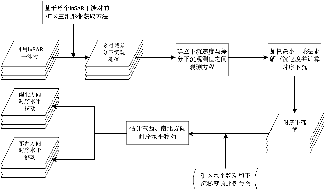
[0043] The following will be combined with figure 1 The present invention is further described.

[0044] Step 1: Use a single radar imaging geometry SAR image to generate a usable InSAR interferometric pair;

[0045] Assuming that there are n+1 single radar imaging geometric SAR images covering the mining area to be monitored, the acquisition time is (t 0 ,t 1 ,...,t n ) (where t 0 1 n ).

[0046] Set the time baseline and spatial baseline thresholds of InSAR interferometric pairs, and use SAR images to generate available InSAR interferometric pairs whose temporal baselines and spatial baselines are smaller than the corresponding thresholds. Assume that the number m of InSAR interferometric pairs available covers the entire time domain process (i.e. from time t 0 to t n During the period, InSAR interference pairs were covered). Let IM and IS respectively denote the time indexes that form m available InSAR interferometric pairs, namely

[0047]

[0048] in, and ...


PUM


Abstract

The invention discloses a mining area three-dimensional sequential deformation monitoring method based on a single radar imaging geometric SAR image. Single radar imaging geometric SAR data is used to generate a usable InSAR interference pair, and mining area surface multi-time-domain differential subsidence observation values are generated. An observation equation between the subsidence velocities and multi-time domain subsidence observation values between adjacent SAR images periods is established, and a weighting least square method is used to solve the subsidence velocities. The sequential subsidence of the mining area surface at the time of SAR image acquisition is calculated using the solved subsidence velocities. Based on the relation that the horizontal movements of the mining area surface in the east, west, south and north directions and the subsidence are in proportion in the corresponding directions, the sequential deformation in the east, west, north and south directions is estimated using the calculated mining area sequential subsidence. The method of the invention realizes the use of single radar imaging geometrical SAR data to monitor three-dimensional sequential deformation of the mining area surface, and greatly lowers the requirements of usage of imaging geometrical SAR data of three or more different radars in the traditional methods.

Description

technical field [0001] The invention relates to a three-dimensional time-series deformation monitoring method in a mining area based on a single radar imaging geometry SAR image. Background technique [0002] Three-dimensional time-series deformation monitoring of the mine surface plays an important role in early assessment and control of potential geological disasters and damage to buildings and structures caused by underground mining. The use of traditional geodetic techniques (such as GPS, leveling, etc.) to monitor the three-dimensional time-series deformation of the mining area surface is not only costly and inefficient, but also has a small monitoring range. Synthetic aperture radar interferometry (Interferometric Synthetic Aperture Radar, referred to as InSAR) is a remote sensing technology that can obtain centimeter or even millimeter-scale deformation of the ground surface. The basic principle is to extract the line-of-sight (LOS) of centimeters or even millimeters...

Claims


Application Information

Patent Timeline
Patent Type & Authority Patents(China)
IPC IPC(8): G01S13/90
CPCG01S13/904G01S13/9023
Inventor 杨泽发朱建军李志伟胡俊
Owner CENT SOUTH UNIV
Learn More