Electromagnetic induction principle based self-chargingwireless mouse and charging method

A wireless mouse and electromagnetic induction technology, applied in battery circuit devices, electrical digital data processing, input/output process of data processing, etc., can solve the problems of insufficient power, inability to save power, single charging method of the mouse, etc., and achieve portability Strong and stable effect

Pending Publication Date: 2016-12-14
SOUTH CHINA UNIV OF TECH
5 Cites 2 Cited by

AI-Extracted Technical Summary

Problems solved by technology

[0004] At present, there are basically two types of rechargeable wireless mice. The first is to embed a rechargeable battery inside the mouse. Although the use of dry batteries is reduced, it still cannot save power; ...

Method used

[0038] The rectifier bridge is composed of 1N4001 rectifier diodes, and the supercapacitor is 0.47F, which has a very strong power storage capacity. The energy storage module stores the electric energy generated by the multi-channel power generation module in the supercapacitor. The power display module us...

Abstract

The invention discloses an electromagnetic induction principle based self-chargingwireless mouse and a charging method. The electromagnetic induction principle based self-chargingwireless mouse comprises a wireless mouse body, a multi-way power generating module, an energy storage module, a selecting switch, a self-learning household appliance remote control module and an electric quantity display module, wherein the multi-way power generating module is connected with the energy storage module, the energy storage module is connected with the electric quantity display module and the wireless mouse body respectively, the multi-way power generating module comprises more than one of waggle power generating unit, a displacement power generating unit, a knocking power generating unit and a rotary power generating unit. When the mouse is used, four power generating modes are alternatively or simultaneously adopted for power generation, and the stability of the power supply of the mouse is ensured.

Application Domain

Batteries circuit arrangementsElectric power +2

Technology Topic

Electromagnetic inductionEngineering +5

Image

  • Electromagnetic induction principle based self-chargingwireless mouse and charging method
  • Electromagnetic induction principle based self-chargingwireless mouse and charging method

Examples

  • Experimental program(1)

Example Embodiment

[0028] Example
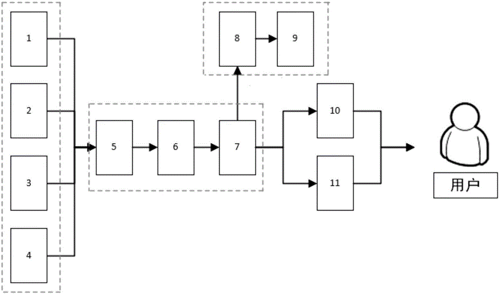
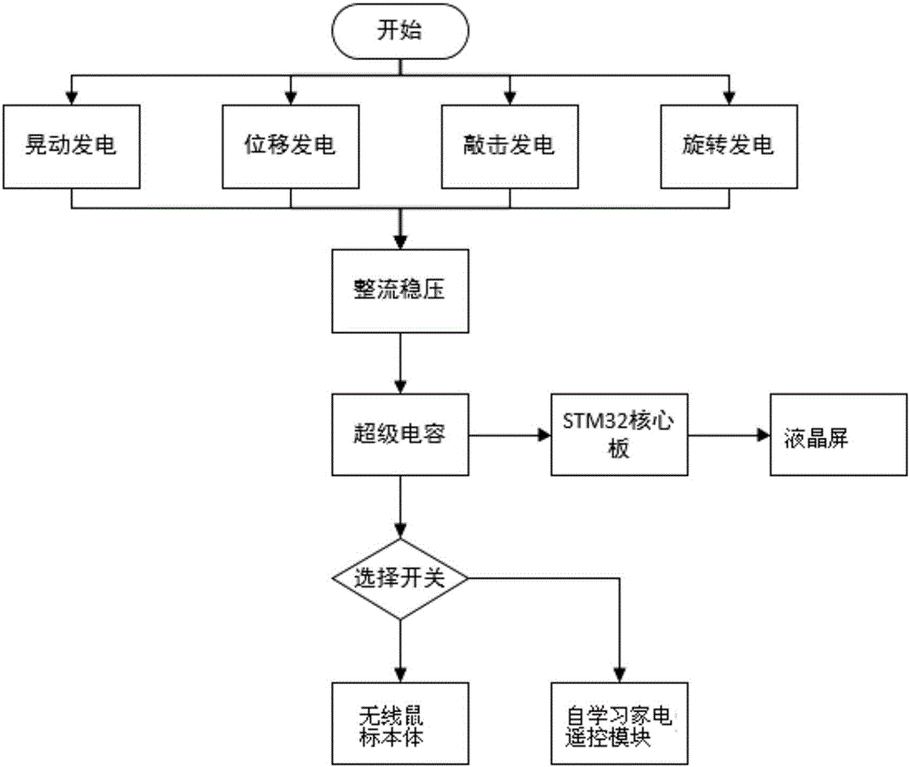
[0029] Such as figure 1 and figure 2 As shown, a self-charging wireless mouse based on the principle of electromagnetic induction includes a wireless mouse body 10, a multi-channel power generation module, an energy storage module, a selection switch, a self-learning home appliance remote control module 11, and a power display module. The multi-channel power generation module Connected to the energy storage module, the energy storage module is respectively connected to the power display module and the wireless mouse body. The multi-channel power generation module includes one of the shaking power generation unit 1, the displacement power generation unit 2, the knock power generation unit 3, and the rotation power generation unit 4. More than species.
[0030] The shaking power generating unit is composed of a first powerful magnet and a first power generating coil built into the body of the wireless mouse;
[0031] The displacement generating unit is composed of a second generating coil built into the body of the wireless mouse and a second powerful magnet located under the mouse pad;
[0032] The percussion power generation unit is composed of a piezoelectric ceramic sheet built into the body of the wireless mouse for converting the left and right buttons of the mouse into electric energy;
[0033] The rotating power generation unit is composed of a motor built into the body of the wireless mouse for converting the scrolling of the mouse wheel into electric energy.
[0034] The selection switch is respectively selectively connected with the self-learning home appliance remote control module and the wireless mouse body.
[0035] The energy storage module is composed of a rectifier bridge 5, a Zener diode 6 and a super capacitor 7 connected in sequence.
[0036] The power display module is composed of an STM32 core board 8 and a 12864 display screen 9.
[0037] The self-learning home appliance remote control module is composed of AD009-03140317 chip and peripheral circuits.
[0038] The rectifier bridge is composed of 1N4001 rectifier diodes, and the super capacitor is 0.47F, which has a strong power storage capacity. The energy storage module stores the electric energy generated by the multi-channel power generation module in the super capacitor. The power display module uses the STM32 core board to AD convert the power of the super capacitor and displays it on the 12864. The power display module is a removable module. AD009-03140317 has a highly built-in resonator, triode, high-sensitivity learning circuit, storage circuit, suitable for digital remote control.
[0039] The electric energy generated by the multi-channel power generation module is full-wave rectified by leaving a 1N4001 rectifier diode. After voltage stabilization, it charges a 0.47F super capacitor. The movement of the mouse ensures the continuity of power supply.
[0040] The working principle of the self-learning home appliance remote control module is as follows: (1) Measurement of the transmitted signal waveform: The high-speed main control chip collects the original signal very precisely, and at the same time uses a relatively large capacity RAM as the signal buffer. This step Mainly buffer the original signal in RAM; (2) Analyze the signal: analyze the collected signal, such as the period of signal sending, the commonly used high and low time and other parameters for detailed analysis to facilitate the next step of compression; (3) Compression coding, according to the time of common high and low level, special high and low level time, sending cycle, compress and code the original signal; (4) Store signal: store the compressed and coded data in EEPROM.
[0041] A charging method for a self-charging wireless mouse based on the principle of electromagnetic induction includes the following:
[0042] When using the mouse normally, the mouse moves on the mouse pad, and the kinetic energy of the movement drives the first powerful magnet to cut the first power generating coil to generate electricity. At the same time, the second power generating coil and the second strong magnet generate electromagnetic induction to generate electricity. When the user taps the left and right sides of the mouse Key, the piezoelectric ceramic sheet deforms to generate electricity. When the user rolls the mouse wheel, the wheel drives the gear of the motor to generate electricity;
[0043] The generated electric energy is stored in the capacitor through the rectifier diode and the Zener diode;
[0044] The electric energy of the capacitor supplies power to the power display module and the wireless mouse body or the self-learning home appliance remote control module through the selection switch.
[0045] The four power generation modes work in parallel, and the generated electrical energy is stored in a 0.47F super capacitor after passing through a rectifier bridge and a Zener diode; the electrical energy stored in the super capacitor is supplied to a wireless mouse, a power display circuit and a self-learning home appliance remote control module.
[0046] The specific working process is as follows:
[0047] When the mouse is used normally, the four power generation modes alternately or simultaneously generate power. When the mouse moves horizontally, the power generation unit and the displacement power generation unit will work. When the left and right buttons of the mouse are clicked, the power generation unit will work. When the roller is rolled, the rotating power generation unit works. The electric energy generated by the above four power generation methods passes through the rectifier module, and after all rectification, it is further stabilized and input into the super capacitor for storage. The voltage input pin of the STM32 core board samples the voltage across the supercapacitor in real time and performs A/D conversion internally. The percentage of power is calculated by the formula and displayed on the 12864 LCD screen. The calculation method is as follows: the set maximum voltage V max , Real-time sampling voltage V now , The displayed battery percentage is (V now /V max )*100%. The above description is when the selector switch is turned on the mouse.
[0048] When the selector switch is in the remote control block, the connection between the super capacitor and the wireless mouse body is disconnected, and power is supplied to the self-learning remote control module, and the infrared receiving tube of the self-learning module is aimed at the infrared transmitting tube that is being remote controlled by learning. , Press the learning button and long press the remote control button corresponding to the learned function. After learning, you can use the mouse to control the corresponding home appliances, and you can repeatedly control multiple types of home appliances.

PUM

no PUM

Description & Claims & Application Information

We can also present the details of the Description, Claims and Application information to help users get a comprehensive understanding of the technical details of the patent, such as background art, summary of invention, brief description of drawings, description of embodiments, and other original content. On the other hand, users can also determine the specific scope of protection of the technology through the list of claims; as well as understand the changes in the life cycle of the technology with the presentation of the patent timeline. Login to view more.

Similar technology patents

Four-rotor aircraft safety control method based on high-order disturbance observer

ActiveCN110320925AEliminate modeling errorsGuaranteed stability
Owner:NANJING UNIV OF AERONAUTICS & ASTRONAUTICS

Complete locating device for total hip arthroplsty

PendingCN107149490AReduce the chance and degree of loosening or saggingGuaranteed stability
Owner:汤向阳

Classification and recommendation of technical efficacy words

  • Portable
  • Guaranteed stability

A ccd-type colloidal gold immunochromatographic diagnostic test paper quantitative analysis system

InactiveCN102279263AGuaranteed stabilityAddressing Subjective Bias
Owner:杭州顿力医疗器械有限公司

General clamp for abrasive flow polishing of complicated hole surface

InactiveCN104551985AContinuous and stable flowGuaranteed stability
Owner:CHANGCHUN UNIV OF SCI & TECH
Why Eureka
Try Eureka