Antenna array and antenna

An antenna array and antenna technology, applied to antenna arrays, antennas, electrical components, etc., to achieve the effects of increasing gain, realizing miniaturized design, and improving the front-to-back ratio index

Active Publication Date: 2016-12-14
COMBA TELECOM TECH (GUANGZHOU) CO LTD
View PDF3 Cites 5 Cited by
  • Summary
  • Abstract
  • Description
  • Claims
  • Application Information

AI Technical Summary

Problems solved by technology

[0005] The primary purpose of the present invention is to provide an antenna arra...

Method used


Image

  • Antenna array and antenna
  • Antenna array and antenna
  • Antenna array and antenna

Examples


Embodiment 1

[0030] In this embodiment, the antenna array includes at least one first radiating element (not numbered, the same below) and at least one second radiating element (not numbered, the same below), and both the first and second radiation elements are dual The polarized oscillators each include two pairs of dipoles with orthogonal polarizations. In the antenna array, a first radiating element and a second radiating element are arranged in a one-to-one correspondence on the antenna reflector in a juxtaposed manner, so as to construct left and right arrays of antennas.

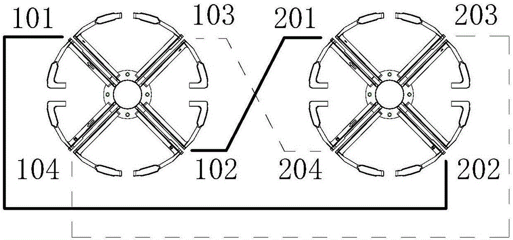
[0031] like figure 1 shown in figure 1 In the figure, the solid line represents the feeder of the antennas in the left column, and the dashed line represents the feeder of the antennas in the right column. Taking a first radiation unit and a second radiation unit arranged flush as an example, the first radiation unit (that is, a dual-polarized oscillator on the left) includes two pairs of dipoles 101, 102, 103, 1...

Embodiment 2

[0038] The antenna array of this embodiment is similar to that of the first embodiment, and the difference lies in:

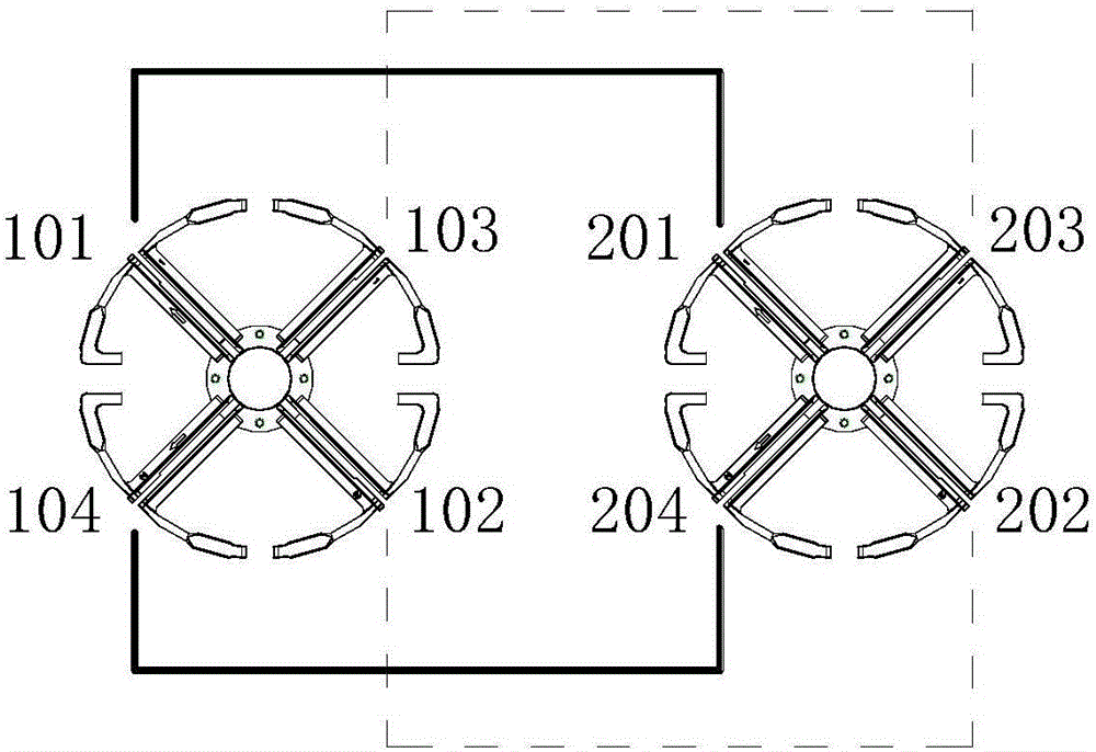
[0039] see figure 2 , in this embodiment, the dipole 101 and the dipole 201 are arrayed in parallel as the positive polarization of the left column antenna. Similarly, dipole 104 and dipole 204 are arrayed in parallel as the negative polarization of the left column antenna, dipole 102 and dipole 202 are arrayed in parallel as the positive polarization of the right column antenna, dipole 103 and dipole The poles 203 are arrayed in parallel as the negative polarization of the right column antenna.

Embodiment 3

[0041] The antenna array of this embodiment is similar to that of the first embodiment, and the difference lies in:

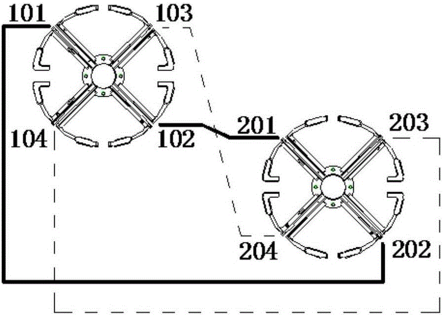
[0042] see image 3 In this embodiment, the first and second radiating elements of the left and right antenna arrays are staggered in the vertical direction, that is, the line connecting the centers of the two dual-polarized oscillators corresponding to the array is a slanted line.


PUM


Abstract

The invention provides an antenna array, which comprises at least one first radiating element and at least one second radiating element, wherein each second radiating element is vertical to the axis of an array in which the first radiating element is located; each first radiating element comprises two pairs of orthogonally polarized dipoles; each second radiating element comprises at least one pair of orthogonally polarized dipoles; and at least one dipole of each first radiating element is connected with one same polarized dipole in each second radiating element through a feeder for shunt feeding through a feed network. A horizontal beam of an antenna can be narrowed to a certain extent by increasing the space between two same polarized dipoles for shunt feeding, so that the problem that the horizontal beam is widened when the antenna size is reduced is solved; the gain and the front-to-rear ratio of the antenna are improved; and miniaturization of the antenna is facilitated. In addition, the invention further relates to the antenna of using the antenna array. The antenna has relatively high gain and front-to-rear ratio and miniaturization is achieved.

Description

technical field [0001] The present invention relates to the technical field of mobile communication antennas, and in particular, the present invention relates to an antenna array and an antenna using the antenna array. Background technique [0002] With the gradual acceleration of the network deployment of 4G mobile communication networks, in order to achieve the improvement of system capacity, the current common implementation method is a MIMO (Multiple-Input Multiple-Output, multiple-input multiple-output) system. Among them, the base station antenna technical solution is to arrange two antenna arrays in parallel. On the basis of the existing technology, in order to ensure the antenna radiation performance, the parallelly arranged antenna arrays have a large spacing, which intuitively shows that the antenna width is huge and occupies a large installation space. [0003] However, with the limitation of station construction space and the increasing difficulty of property coo...

Claims


Application Information

Patent Timeline
IPC IPC(8): H01Q1/36H01Q21/00
CPCH01Q1/36H01Q21/00
Inventor 费锦洲王强陆尧李宗源
Owner COMBA TELECOM TECH (GUANGZHOU) CO LTD
Why Eureka
Try Eureka