Integrated protection method for intelligent substation
An intelligent substation and current technology, applied in emergency protection circuit devices, electrical components, etc., can solve problems such as data loss and data errors, and achieve the effects of accurate identification, strong applicability, and simple calculation.
- Summary
- Abstract
- Description
- Claims
- Application Information
AI Technical Summary
Problems solved by technology
Method used
Image

Examples
Embodiment 1
[0063] Embodiment 1 provides an integrated protection method for a smart substation. When the substation transformer T1 fails and the data transmission is normal, it includes the following steps:
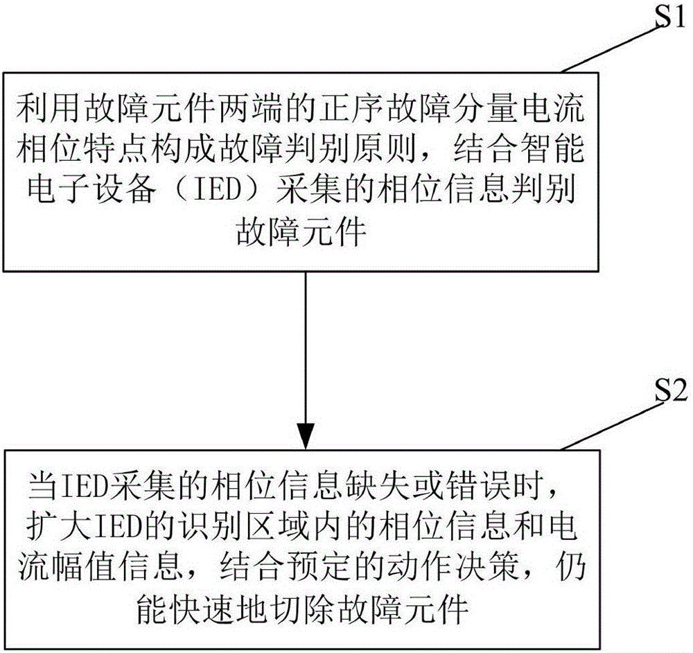
[0064] S1: Utilize the phase characteristics of the positive sequence fault component current at both ends of the fault component, perform phase comparison to constitute the fault discrimination principle, and combine the phase information collected by the intelligent electronic device (IED) to identify the fault component;
[0065] Step S1 includes using the current phase characteristics of positive sequence fault components to form fault discrimination principles combined with phase information collected by intelligent electronic devices (IEDs) to identify faulty components, specifically including:
[0066] S11: It is stipulated that the positive sequence fault component current flowing through the protection is directed from the bus to the line; when the line, bus, and transformer...
Embodiment 2
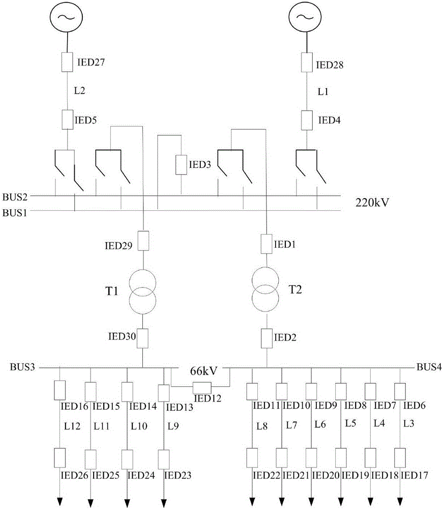
[0093] Embodiment 2 provides an integrated protection method for a smart substation. When the substation transformer T1 fails and the fault phase information collected by the IED30 is lost, the identification of the fault element includes the following steps:
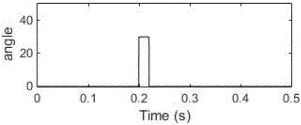
[0094] Collect the positive sequence fault component current information, compare the positive sequence fault component current phases at both ends of each component, and judge the failure of the low-voltage bus or transformer T1 according to the principle of fault component discrimination, and first trip the circuit breaker between the transformer and the low-voltage bus. Figure 5 , Figure 6 , Figure 7 , Figure 8 It is the simulation diagram of the positive sequence fault component current phase comparison value of the transformer high voltage side and low voltage side line output by IED29; Figure 9 The simulation diagram of the output value of the circuit breaker on the low-voltage side of the transformer outpu...
Embodiment 3
[0097] Embodiment 3 provides an integrated protection method for a smart substation. When the substation transformer T1 fails and the low-voltage side fault phase information collected by the IED30 is wrong, the fault component identification includes the following steps:
[0098] Collect the positive sequence fault component current information, compare the positive sequence fault component current phases at both ends of each component, and judge it as a low-voltage bus fault according to the principle of fault component discrimination. between circuit breakers. Figure 15 , Figure 16 , Figure 17 , Figure 18 The simulation diagram of the current phase comparison value of the positive sequence fault component of the low-voltage busbar and its lines output by IED29; Figure 19 The simulation diagram of the output value of the low-voltage bus circuit breaker output by IED29;
[0099] Collect the positive sequence fault component current information again, use the positive...
PUM
 Abstract
Description
Claims
Application Information
 - Generate Ideas
- Intellectual Property
- Life Sciences
- Materials
- Tech Scout
- Unparalleled Data Quality
- Higher Quality Content
- 60% Fewer Hallucinations
Browse by: Latest US Patents, China's latest patents, Technical Efficacy Thesaurus, Application Domain, Technology Topic, Popular Technical Reports.
© 2025 PatSnap. All rights reserved.Legal|Privacy policy|Modern Slavery Act Transparency Statement|Sitemap|About US| Contact US: help@patsnap.com