A control circuit for SCR multi-standby voltage switching

A control circuit and thyristor technology, which is applied in the direction of emergency protection circuit devices, electrical components, etc., can solve the problems of not being able to switch at high frequency, not suitable for frequent work, flashover, etc., and achieve simple and novel lines and better quality control Effect

Active Publication Date: 2019-06-18
GUANGDONG NRE TECH
View PDF5 Cites 0 Cited by
  • Summary
  • Abstract
  • Description
  • Claims
  • Application Information

AI Technical Summary

Problems solved by technology

[0002] Today's thyristor characteristics still have some additional conditions for shutting off. This characteristic of thyristors limits high-frequency switching. Some traditional electrical control cabinets use relays or contactors for switching, and relays or contacts The movable contact and the static contact of the device will flash over when there is a large current contact, which is not suitable for frequent work. The other is to use a solid state relay instead of a relay or contactor. Although the problem of flashover of the contact is solved, it cannot When a device needs to switch its original A power supply to B power supply or C power supply to obtain a different voltage power supply in a short period of 100mS (such as UPS), and this type of solid state relay is actually a thyristor inside. , and the turn-off characteristics of thyristors limit the application in this type of electrical equipment, such as some aging power supply control cabinets used for life cycle acceleration tests and high-current electrical equipment that require rapid switching

Method used


Image

  • A control circuit for SCR multi-standby voltage switching
  • A control circuit for SCR multi-standby voltage switching
  • A control circuit for SCR multi-standby voltage switching

Examples


Embodiment Construction

[0023] The present invention will be further described below with reference to the accompanying drawings and embodiments.

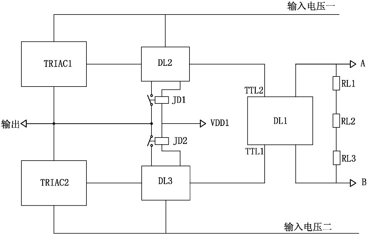
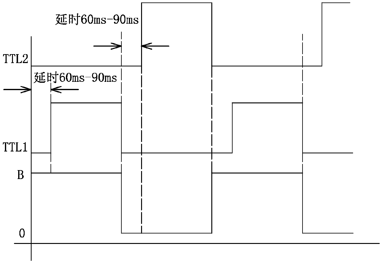
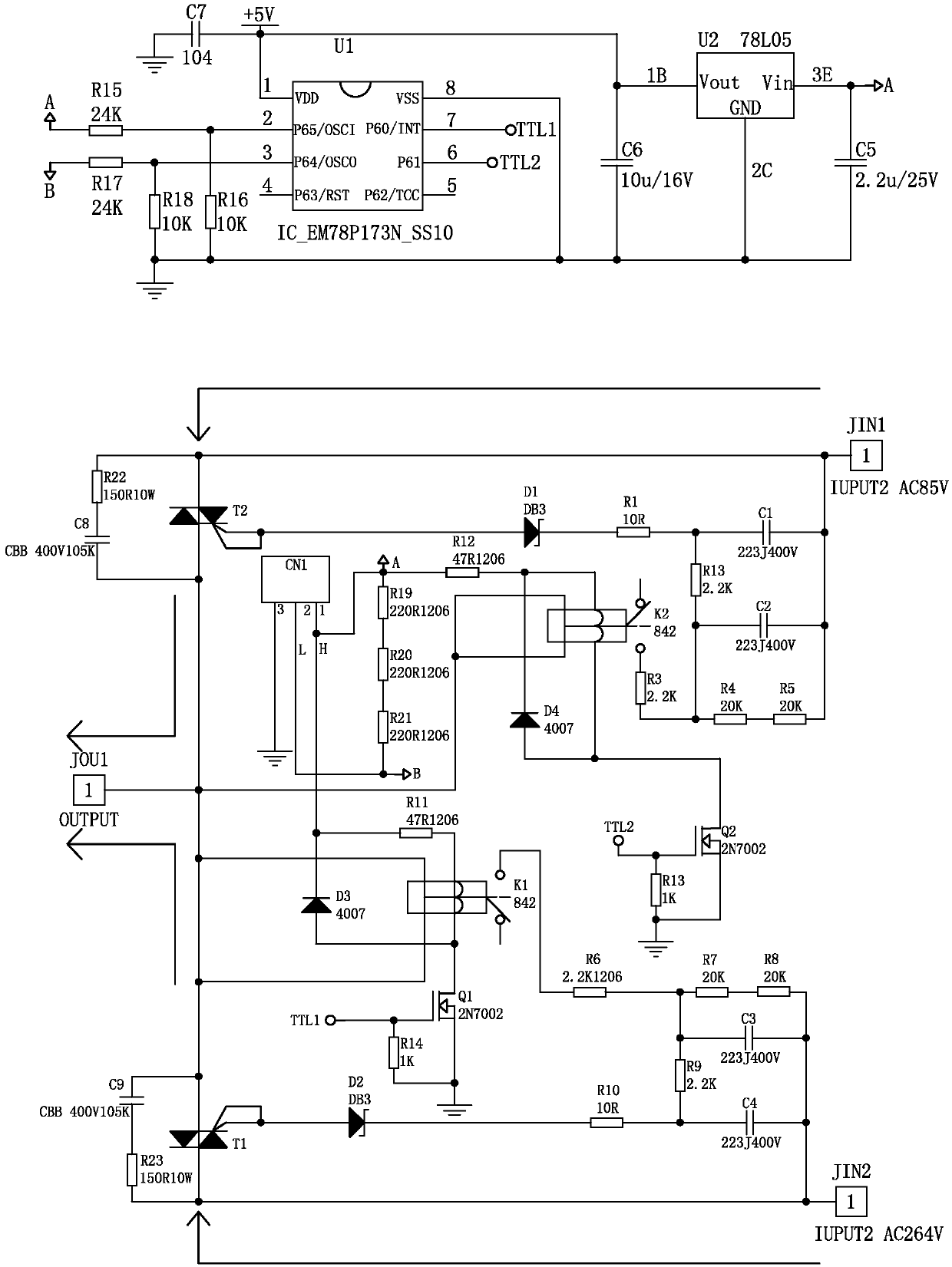
[0024] see Figure 1-Figure 3 , The control circuit for switching multiple thyristors under pressure includes a first thyristor control circuit module TRIAC1 for external output, a second thyristor control circuit module TRIAC2 for external output, a first control isolation relay JD1, a second control circuit Isolation relay JD2 and ICU detection circuit DL1; two thyristor control circuit modules are respectively connected with two control isolation relays to provide control signals, and ICU detection circuit DL1 is respectively connected with two control isolation relays to provide alternate delay control signals; The output terminals of the first thyristor control circuit module TRIAC1 and the second thyristor control circuit module TRIAC2, and the input terminals of the first control isolation relay JD1 and the second control isolation relay JD2 are co...


PUM


Abstract

Disclosed is a control circuit for multi standby voltage switching of a silicon controlled rectifier. The control circuit comprises a first silicon controlled rectifier control circuit module (TRIAC1) for outward output, a second silicon controlled rectifier control circuit module (TRIAC2) for outward output, a first isolation controlling relay (JD1), a second isolation controlling relay (JD2) and an ICU detection circuit (DL1). The two silicon controlled rectifier control circuit modules (TRIAC1, TRIAC2) are respectively connected to the two isolation controlling relays (JD1, JD2) so as to provide control signals. The ICU detection circuit (DL1) is respectively connected to the two isolation controlling relays (JD1, JD2) so as to provide alternate time-delay control signals. Output ends of the first silicon controlled rectifier control circuit module (TRIAC1) and the second silicon controlled rectifier control circuit module (TRIAC2), and input ends of the first isolation controlling relay (JD1) and the second isolation controlling relay (JD2) are connected to the same node. A power source of the control circuit realizes ordered work by means of a working relation between voltage differences, and performs isolation control by means of a signal-type relay. Neither a switch from a low voltage to a high voltage or a switch from a high voltage to a low voltage of an output and conversion silicon controlled rectifier will enable the other silicon controlled rectifier to be in an instant conductive state.

Description

technical field [0001] The invention relates to the technical field of electrical equipment, in particular to a control circuit for switching multiple voltages of thyristors. Background technique [0002] Today's thyristor characteristics still have some additional conditions for turning off. This characteristic of thyristor limits the inability to switch at high frequencies. Some traditional electrical control cabinets use relays or contactors for switching, while relays or contactors are used for switching. When the moving contact and the static contact of the device are in contact with a large current, there will be flashover, which is not suitable for frequent work. The other is to replace the relay or contactor with a solid state relay. When a device needs to switch from its original A power supply to B power supply or C power supply to obtain a different voltage power supply in a very short 100mS time (such as UPS), and this type of solid state relay is actually a thyr...

Claims


Application Information

Patent Timeline
Patent Type & Authority Patents(China)
IPC IPC(8): H02H11/00
CPCH02H11/00
Inventor 曾维建
Owner GUANGDONG NRE TECH
Why Eureka
Try Eureka