Check patentability & draft patents in minutes with Patsnap Eureka AI!

Photocatalytic Micro-Gas-Liquid Bubble Column Reactor

A technology of photocatalysis and bubble tower, which is applied in the field of photocatalysis, can solve the problems of enhanced processing capacity, difficulty in separation and recovery, and long reaction time, and achieve the effects of large processing capacity, accelerated reaction rate, and improved mass transfer coefficient

Active Publication Date: 2018-01-23
TIANJIN UNIV
View PDF11 Cites 0 Cited by
  • Summary
  • Abstract
  • Description
  • Claims
  • Application Information

AI Technical Summary

Problems solved by technology

Chinese patent CN200610029643.4 (Jin Litong, etc., East China Normal University, capillary array photocatalytic reactor and its preparation and application), Chinese patent 200910197401.X (Wang Hongzhi, Donghua University, micro-channel photocatalytic reactor based on nanorod array Catalytic microreactor and preparation method thereof) and 201010148412.1 (Shang Jintang et al., Southeast University, preparation method of photocatalytic microreactor) both use microchannels as the reaction area, which has a small light receiving area, low processing capacity of a single microchannel, and parallel amplification Difficulty and other issues
Chinese patent 201210051512.1 (Ma Xiaoxun et al., Northwest University, titanium dioxide photocatalytic microreactor) provides a parallel amplification method, but there is a limitation of the effective propagation distance of light with optical fiber as the channel of light (AIChE J.2006,52(6 ):2271-2280), or it is necessary to set up a built-in light source with a complex structure, and the reactor is operated intermittently, etc.
Chinese patent CN201410415832.X invented a flat photocatalytic microreactor (Liu Mingyan et al., Tianjin University, a method for preparing a titanium dioxide plate photocatalytic microreactor doped with metal ions and a catalyst film in the reactor), and its treatment Capacity needs to be strengthened
Due to the large characteristic size of the macroscopic photocatalytic bubble column reactor, light attenuation is serious when passing through the solution or catalyst particles, which will lead to low catalytic efficiency, the need to circulate the reaction liquid, and long reaction time (>1h), etc.
Second, although the nano-catalyst particles commonly used in such reactors are effective, their separation and recovery are difficult and costly

Method used


Image

  • Photocatalytic Micro-Gas-Liquid Bubble Column Reactor
  • Photocatalytic Micro-Gas-Liquid Bubble Column Reactor
  • Photocatalytic Micro-Gas-Liquid Bubble Column Reactor

Examples


Embodiment 1

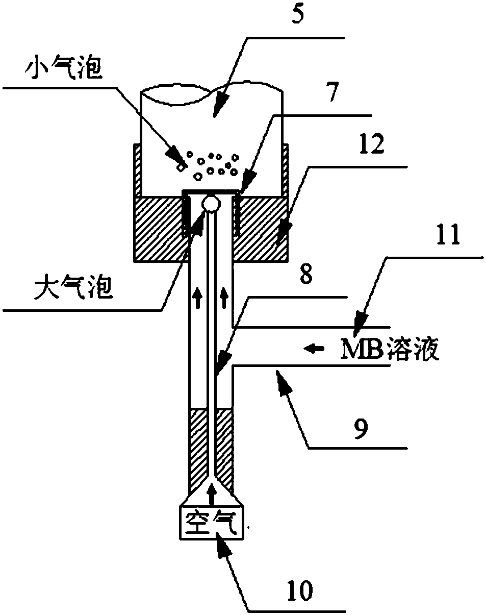
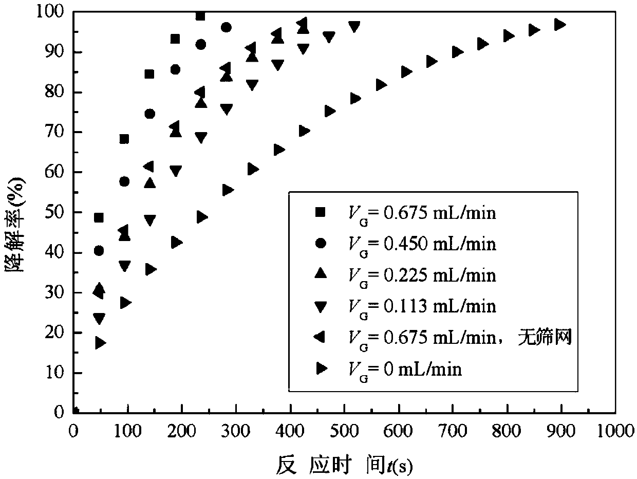
[0022] Methylene blue (MB) was selected as the reactant to investigate the photocatalytic activity of the photocatalytic micro gas-liquid bubble column reactor. The inner diameter of the quartz tube is 3mm, the length is 100mm, the length of the reflector is 150mm, the inner diameter of the T-shaped tee is 2mm, the inner diameter of the needle tube 8 is 0.13mm, and the aperture of the screen is 0.053mm. During the operation of the photocatalytic micro-bubble column reactor, the power of the xenon lamp is 200W, and the initial concentration of the MB solution is C 0 20mg·L -1 , the flow rate Q is 0.900mL·min -1 , the flow rate of air V G 0.013, 0.225, 0.450 and 0.675mL min -1 , corresponding to the superficial liquid velocity u L 0.027, 0.053, 1.06 and 1.59mm s respectively -1 . The large air bubbles at the top of the needle tube 8 are quickly separated from the needle tube 8 and passed through the screen 7 under the impetus of the liquid in the needle tube and the three-...


PUM


Abstract

The invention discloses a photo-catalytic micro gas-liquid bubble column reactor, comprising a quartz tube and a gas distributor, wherein a catalyst film is carried on the inner wall of the catalyst tube, the gas distributor comprises a T joint, a screen is fixed at a top outlet of the T joint, a needle tube is arranged vertically in the middle of a vertical tube of the T joint, the lower part of the quartz tube is connected with the upper part of the vertical tube of the T joint by a groove tube, the groove tube comprises a groove formed in the internal upper part of the groove tube, a middle hole running through the groove is formed in the middle of the bottom wall of the groove, the lower part of the quartz tube is fixed in the groove, the upper part of the vertical tube of the T joint is inserted into the middle hole, an expanding section is arranged at the top of the quartz tube, the expanding section is provided with a liquid outlet, a light source is arranged in front of the quartz tube, and a parabolic reflector is arranged in back of the quartz tube. Stable bubbly flow is formed by adopting the reactor, so that the mass transfer coefficient is increased by times.

Description

technical field [0001] The invention relates to the technical field of photocatalysis, in particular to the photocatalytic tiny gas-liquid bubble column reactor and the gas distributor technology thereof. Background technique [0002] Microreactors have been applied in the field of photocatalysis immediately since their advent in the 1990s. The characteristic size of photocatalytic microreactor is below 1mm (Chem.Eng.Sci.,2001,(56):293-303), which has many advantages, such as high specific surface area (>10000m 2 / m 3 ), high mass and heat transfer rates, and small uniform light attenuation (Lab on a Chip, 2001, 1(1): 22-28; AIChE J., 2007, 53(3): 695-700; Chem. Eng. J., 2008, 135(4):S303-S308). However, it also has some obvious disadvantages. First, compared with the suspended catalyst particles, the phase boundary area of ​​the catalyst loaded on the inner surface of the microchannel is very small; second, the characteristic size of the microreactor determines that ...

Claims


Application Information

Patent Timeline
Patent Type & Authority Patents(China)
IPC IPC(8): B01J19/00B01J19/12
CPCB01J19/0093B01J19/12B01J2219/00835
Inventor 刘明言杨中国王晓云
Owner TIANJIN UNIV
Features
  • R&D
  • Intellectual Property
  • Life Sciences
  • Materials
  • Tech Scout
  • Unparalleled Data Quality
  • Higher Quality Content
  • 60% Fewer Hallucinations
Learn More