
Planing method for cubic part vertical faces

A vertical surface and cube technology, applied in the field of mechanical processing, can solve problems that affect processing accuracy, cannot use grinding machines, workpiece deformation, etc., to achieve the effects of ensuring processing quality, improving precision, and reducing deformation

Active Publication Date: 2016-12-21
HARBIN
View PDF6 Cites 3 Cited by
  • Summary
  • Abstract
  • Description
  • Claims
  • Application Information

AI Technical Summary

Problems solved by technology

The grinding method can be used to further finish the parts that can be clamped and fixed by the magnetic chuck, but the workpiece is deformed when the grinder is magnetically attracted, and when the grinding is completed, the deformation of the workpiece rebounds with the disappearance of the magnetic force, which affects Machining accuracy, and some workpieces cannot be grinded
Fine milling and CNC machining are more prone to residual stress, resulting in deformation of the workpiece

Method used


Image

  • Planing method for cubic part vertical faces
  • Planing method for cubic part vertical faces
  • Planing method for cubic part vertical faces

Examples


Embodiment Construction

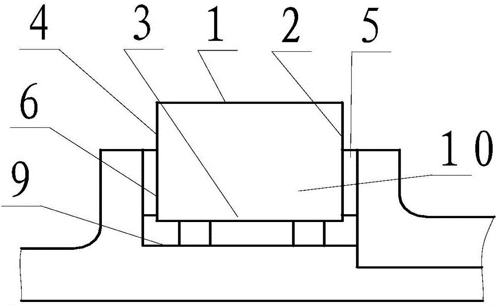
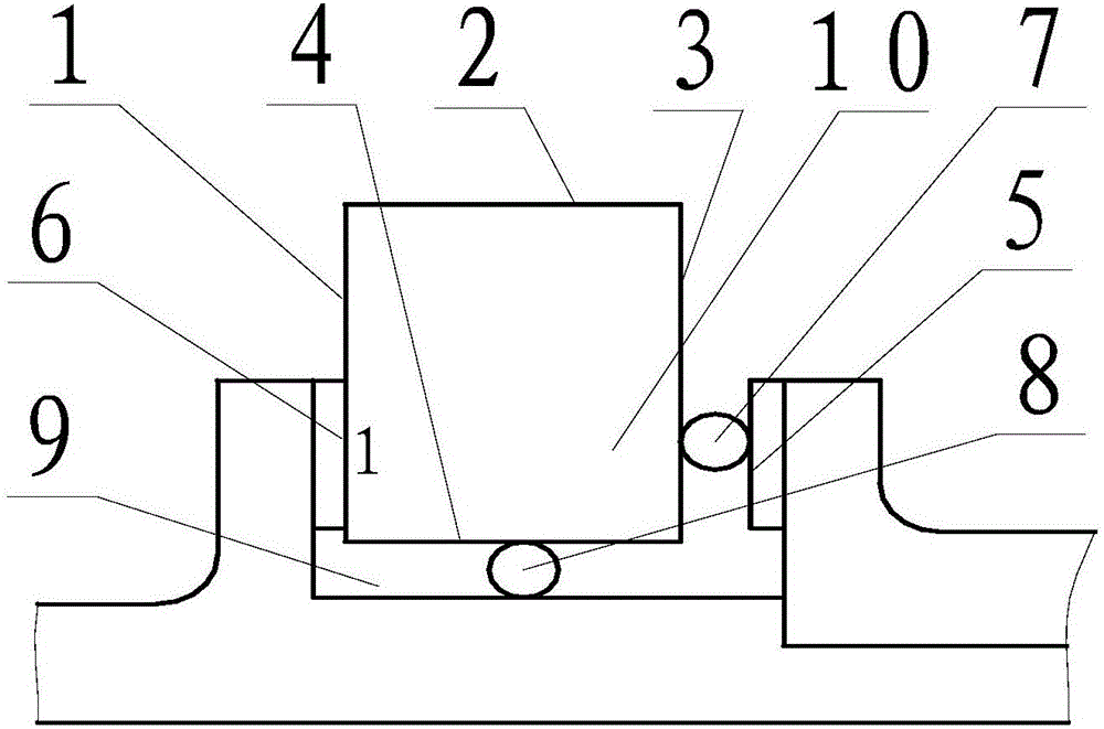
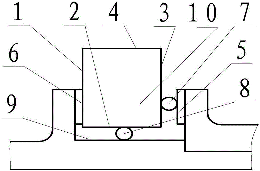
[0017] The present invention will be described in further detail below. see figure 1 , figure 2 , image 3 , Figure 4 , a planing method for a vertical surface of a cube part, comprising:

[0018] 1.1. Inspection and calibration clamps: Install the flat-nose pliers on the planer workbench, clamp the dial indicator on the planer tool holder, check the verticality of the jaws of the flat-nose pliers by moving the tool holder up and down on the machine tool, and check by moving the tool holder horizontally If there is deviation in the straightness of the jaws of the flat-nose pliers, adjust it until it is qualified, and fix the flat-nose pliers on the workbench.

[0019] 1.2. Rough planing four vertical surfaces: Clamp the workpiece 10 rough planing four sides according to the traditional method, leaving about 0.5mm fine planing allowance on each side.

[0020] 1.3. Planing a horizontal plane: select the relatively flat and large surface 1 in the length direction as the ro...


PUM


Abstract

The invention belongs to machining technology and relates to improvement to planing methods for cubic part vertical faces. A planing method for cubic part vertical faces comprises the steps that a gripper is detected and rectified; rough planing is conducted on four vertical faces; a horizontal face is planed; one vertical face is planed; the other vertical face is planed; and the other horizontal face is planed. According to the planing method, the perpendicularity of the vertical face of the gripper and horizontal cutter feeding of a machine tool is used, one vertical face of the gripper is used as the datum, all the vertical faces are machined, the principle of datum unification is achieved, and thus the perpendicularity requirements of the four machined cubic part faces are met. Through filling of a round bar, clamping force is focused on the middle of a jaw so that a datum plane can be attached to the fixed jaw tightly and reliably, and thus the machining quality is ensured. The planing method is simple and convenient to operate, the precision of a machined part can be improved, and deformation of machining is reduced effectively.

Description

technical field [0001] The invention relates to the technical field of machining. Background technique [0002] In the field of mechanical processing, sometimes the four vertical long faces of long cube parts are processed. Because ordinary planers and milling machines can only ensure the flatness and parallelism when processing the plane parallel to the worktable, when the workpiece is turned over, the processed vertical face The perpendicularity requirement with the previously processed surface cannot be guaranteed. Subsequent finishing can only be done by grinding or CNC. The grinding method can be used to further finish the parts that can be clamped and fixed by the magnetic chuck, but the workpiece is deformed when the grinder is magnetically attracted, and when the grinding is completed, the deformation of the workpiece rebounds with the disappearance of the magnetic force, which affects Processing accuracy, and some workpieces cannot be used with grinding machines. ...

Claims


Application Information

Patent Timeline
IPC IPC(8): B23D7/00
CPCB23D7/00
Inventor 陈永志李广伟刘维俭杨春光李凤霄孙滔
Owner HARBIN
Learn More