Machining method for engine connecting rod

A technology of engine connecting rods and processing methods, which is applied in the direction of connecting rods, mechanical equipment, shafts and bearings, can solve the problems of reduced reliability and durability of connecting rods, high processing precision requirements, and increased processing costs of connecting rods, etc., to achieve The effect of improving levelness and increasing strength

Active Publication Date: 2016-12-21
苏州利达铸造有限公司
View PDF5 Cites 4 Cited by
  • Summary
  • Abstract
  • Description
  • Claims
  • Application Information

AI Technical Summary

Problems solved by technology

There are many overall processing procedures, and the high processing accuracy requirements for the connecting rod body, the connecting rod cover surface and the bolt hole lead to an increase in the processing c

Method used


Image

  • Machining method for engine connecting rod
  • Machining method for engine connecting rod

Examples


Example Embodiment

[0016] Example 1

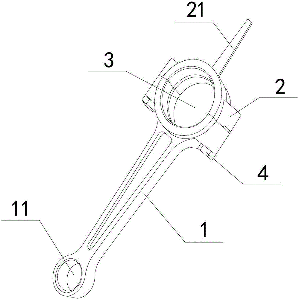
[0017] Such as figure 1 The engine connecting rod shown includes a connecting rod body 1 and a connecting rod cover 2 installed at the end of the connecting rod body 1. The connecting rod body 1 and the connecting rod cover 2 are connected by a plurality of bolts 4 installed on the side of the connecting rod body 1 , The connecting rod body 1 and the connecting rod cover 2 are provided with a large-head hole 3, the other end of the connecting rod body 1 is provided with a small-head hole 11, and the center of the large-head hole 3 is at the break of the connecting rod body 1 and the connecting rod cover 2. In the plane; the connecting rod cover 2 is also integrally connected with a thimble rod 21 on the same straight line as the connecting rod body 1.

[0018] The machining method of the above engine connecting rod can generally refer to the method and equipment in CN201310021032.5, including the following steps:

[0019] (A) Roughly grinding both ends of the con...

Example Embodiment

[0023] Example 2

[0024] This embodiment provides a method for processing the connecting rod of the engine in Example 1. The steps are basically the same as those in Example 1, except that the connecting rod is heated to 150°C, and the hydraulic cylinder drives the two-way wedge downward. Move and press into the semicircular moving sleeve and push the semicircular moving sleeve to act on the inner wall of the big head hole 3. The big head hole 3 is instantly broken and the connecting rod cover 2 separates from the connecting rod body 1, and is poured with cold water (30°C).

Example Embodiment

[0025] Example 3

[0026] This embodiment provides a method for processing the connecting rod of the engine in Example 1. The steps are basically the same as those in Example 1, except that the connecting rod is heated to 200°C, and then the hydraulic cylinder drives the bidirectional wedge downward. Move and press into the semicircular moving sleeve and push the semicircular moving sleeve to act on the inner wall of the big head hole 3. The big head hole 3 is instantly broken and the connecting rod cover 2 separates from the connecting rod body 1, and it is poured with cold water (20°C).


PUM

PropertyMeasurementUnit
Diameteraaaaaaaaaa

Abstract

The invention relates to a machining method for an engine connecting rod. The machining method for the engine connecting rod includes the following steps that (a) the two end surfaces of the connecting rod are subjected to rough grinding, a small-head hole is drilled and enlarged, a large-head hole and the small-head hole are subjected to rough boring, the small-head hole is subjected to semi-finished boring, a bolt boss is milled, a bolt hole is drilled or tapped, and deburring is carried out; (b) linear cutting is carried out on the position, corresponding to a cracking plane, of the inner edge of the large-head hole to form a V-shaped cracking groove, and the V-shaped cracking groove is symmetrical relative to the cracking plane to form an initial cracking source; (c) the connecting rod is heated to 150-250 DEG C, a hydraulic cylinder drives a bidirectional wedge block to move downwards and be pressed into a semicircular movable sleeve, the semicircular movable sleeve is pushed to act on the inner wall of the large-head hole, the large-head hole is cracked instantly, a connecting rod cover and a connecting rod body are separated, and cold water is sprayed; and (d) the cracked connecting rod is subjected to fine machining, and a cracked connecting rod finished product is formed. The connecting rod is heated and sprayed with the cold water after the connecting rod cover and the connecting rod body are separated, the strength of the engine connecting rod can be improved, and the levelness of the cracking plane of the connecting rod cover and the connecting rod body can be improved as well.

Description

technical field [0001] The invention belongs to the processing field of metal parts, and in particular relates to a processing method of an engine connecting rod. Background technique [0002] The connecting rod is one of the important moving parts of the engine. Its function is to transmit the gas pressure on the piston to the crankshaft, and convert the reciprocating motion of the piston into the rotational motion of the crankshaft to output power externally. Therefore, it mainly carries the gas deflagration in the cylinder. The impact force of the crankshaft and the inertial force of the crankshaft rotation need to withstand alternating loads such as compression, tension, and bending. [0003] In order to ensure that the crankshaft under high-speed operation is always in a balanced state and to facilitate the quality grouping of the connecting rods after processing, the connecting rods not only have high dimensional accuracy requirements, but also have strict control over...

Claims


Application Information

Patent Timeline
IPC IPC(8): B23P15/00
CPCB23P15/00B23P2700/04
Inventor 季吉清
Owner 苏州利达铸造有限公司
Why Eureka
Try Eureka