Building concrete mixing and stirring device and operation method thereof

A technology for mixing and mixing concrete, which is applied to cement mixing devices, clay preparation devices, unloading devices, etc. It can solve the problems of limited work sites, low work efficiency, and low stability, so as to reduce labor intensity and overcome the use of site restrictions, the effect of improving stability

Inactive Publication Date: 2016-12-21
芜湖瑞德机械科技有限公司
View PDF5 Cites 9 Cited by
  • Summary
  • Abstract
  • Description
  • Claims
  • Application Information

AI Technical Summary

Problems solved by technology

[0003] The purpose of the present invention is to provide a concrete mixer with reasonable structure design, wide application range, good mixing quality, Concrete mixing device for construction with high stability and not restricted by working site and operation method thereof

Method used


Image

  • Building concrete mixing and stirring device and operation method thereof
  • Building concrete mixing and stirring device and operation method thereof

Examples


Embodiment 1

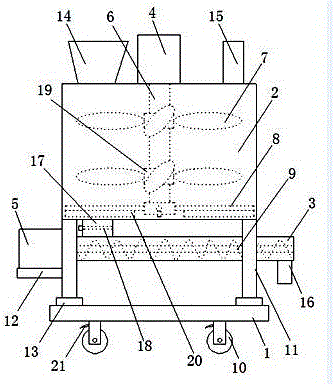
[0022] as attached figure 1 As shown, a concrete mixing and stirring device for construction includes a base plate 1, a mixing chamber 2, a feeding cylinder 3, a motor one 4, a motor two 5, a transmission shaft 6, a stirring blade 7, a material rod 8, and an auger 9 And roller 10, it is characterized in that, described base plate 1 is provided with support 11, and is provided with bearing plate 12 on support 11, and described base plate 1 and support 11 are provided with shock pad 13, described Shock-absorbing pad 13 is set to polymer rubber material, and described mixing chamber 2 is arranged on the support 11, and is provided with feeding bin 14, water inlet pipe 15 on mixing chamber 2, and described feeding tube 3 one end Connect with the mixing chamber 2 through the feeding pipe 17, the other end is provided with the discharging pipe 16, the valve 18 is arranged in the described feeding pipe 17, and the described motor one 4 is arranged on the mixing chamber 2, so The mot...

Embodiment 2

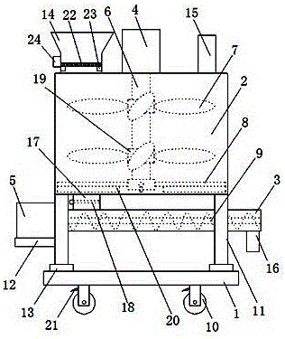
[0030] as attached figure 2As shown, a concrete mixing and stirring device for construction includes a base plate 1, a mixing chamber 2, a feeding cylinder 3, a motor one 4, a motor two 5, a transmission shaft 6, a stirring blade 7, a material rod 8, and an auger 9 , roller 10 and sieve plate 22, it is characterized in that, described base plate 1 is provided with support 11, and is provided with bearing plate 12 on support 11, and described base plate 1 and support 11 are provided with shock pad 13 , the shock-absorbing pad 13 is provided with a shock-absorbing spring, the mixing chamber 2 is arranged on the bracket 11, and a feeding bin 14 and a water inlet pipe 15 are arranged on the mixing chamber 2, and the feeding A vibrating motor 23 is arranged in the bin 14, and a miscellaneous outlet 24 is arranged on the outer wall of the feeding bin 14. One end of the transfer cylinder 3 is connected with the mixing chamber 2 through a feeding tube 17, and an outlet port 24 is arr...


PUM


Abstract

The invention discloses a building concrete mixing and stirring device which comprises a bottom plate, a mixing chamber, a transfer barrel, a motor I, a motor II, a transmission shaft, stirring blades, a shifting rod, an auger and idler wheels. The building concrete mixing and stirring device is characterized in that a bracket is arranged on the bottom plate, the mixing chamber is arranged on the bracket, one end of the transfer barrel is connected with the mixing chamber through a blanking pipe, a discharge pipe is arranged at the other end of the transfer barrel, the motor I is arranged on the mixing chamber, the motor II is arranged on a loading plate, the transmission shaft is arranged in the mixing chamber, and one end of the transmission shaft is connected with the motor I. The stirring blades and the shifting rod are arranged on an installation block of the transmission shaft, a scraping plate is arranged on the shifting rod, and concrete in the mixing chamber is sufficiently stirred through the stirring blades, so that the concrete material is fully mixed with water to improve the stirring degree of the concrete, the concrete in the mixing chamber is fully discharged through the shifting rod and the scarping plate on the shifting rod, and the waste of the concrete is reduced.

Description

technical field [0001] The invention relates to the technical field of concrete processing, in particular to a concrete mixing device for construction and an operation method thereof. Background technique [0002] Concrete mixers are mechanical equipment used to mix and stir cement, sand and water into concrete mixtures, and are widely used on construction sites. Using a mechanized concrete mixer to mix cement can save a lot of manpower and material resources. When the existing concrete mixer is in use, there are problems such as that the raw material is easy to agglomerate when the raw material is mixed, the stability of the mixer is not high during the mixing and mixing process of the concrete raw material, the mixing is uneven, and the work site is limited. For example, the patent application number 201520198907.8 discloses a concrete mixer, which solves the problems of complex structure and high cost of the concrete mixer, but it has the problems of low work efficiency,...

Claims


Application Information

Patent Timeline
Patent Type & Authority Applications(China)
IPC IPC(8): B28C5/16B28C5/08B28C7/16B28C5/00
CPCB28C5/16B28C5/006B28C5/0806B28C5/0831B28C5/0856B28C7/167
Inventor 杜京奎胡已生易建鑫
Owner 芜湖瑞德机械科技有限公司
Why Eureka
Try Eureka