
Supercharger execution control structure and control method thereof

A technology of executive control and supercharger, which is applied in the direction of machines/engines, internal combustion piston engines, mechanical equipment, etc., can solve the problems of precision control error, influence on control accuracy, large error, etc., and achieve safety and reliability improvement and reduction Probability of failure, effect of improving response speed

Inactive Publication Date: 2016-12-21
CHERY COMML VEHICLE ANHUI
View PDF5 Cites 2 Cited by
  • Summary
  • Abstract
  • Description
  • Claims
  • Application Information

AI Technical Summary

Problems solved by technology

[0002] The existing supercharger actuator control method, one is to convert the required pressure into the duty cycle of the three-way solenoid valve, and control the pressure inside the pneumatic mold box through the duty cycle to control the opening of the air release valve and then control The supercharging pressure meets the demand pressure, and the precise control of the supercharging pressure cannot be realized, and the error is relatively large; the other is to calculate the required power of the compressor according to the demand pressure by calculating the size of the demand pressure, and calculate the power of the turbine through efficiency conversion. Calculating the demanded waste gas valve opening through the turbine power, but this opening model requires an external sensor for accurate calibration. The demanded opening is calculated through the model and then converted into the duty cycle of the three-way solenoid valve, and then converted into the pressure of the control mold box Then control the boost pressure to meet the demand pressure, the actuator does not have a position sensor, the required actuator opening can only be calculated through a mathematical model, and there are also errors in precision control, which affect the control accuracy

Method used


Image

  • Supercharger execution control structure and control method thereof
  • Supercharger execution control structure and control method thereof

Examples


Embodiment Construction

[0021] The specific implementation manner of the present invention will be described in further detail below by describing the embodiments with reference to the accompanying drawings.

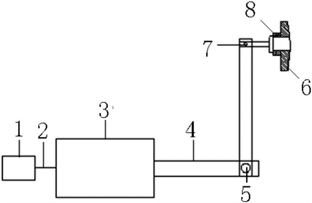
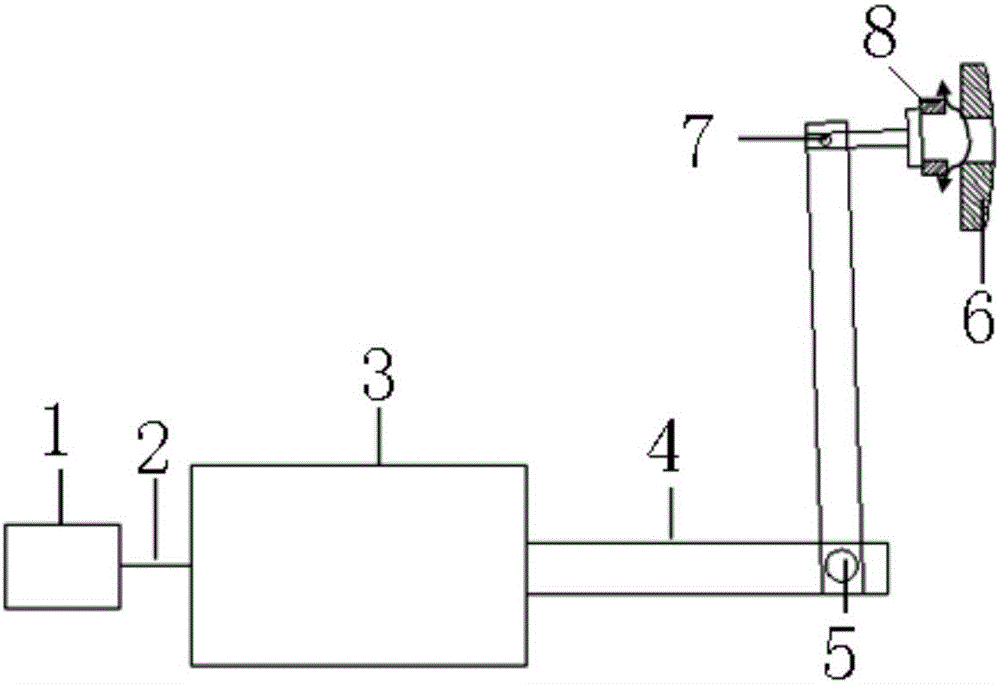
[0022] like figure 1 and figure 2 As shown, the supercharger execution control structure includes an ECU control unit 1, a supercharger waste gas release valve and an electronically controlled actuator 3, wherein the supercharger waste gas release valve includes a matching supercharger waste gas release valve Seat 6 and exhaust gas release valve 8, there is a guide rod between the supercharger waste gas release valve seat 6 and exhaust gas release valve 8, and the electric control actuator is an electric control actuator with self-locking function to ensure the opening control accurate.

[0023] The control unit 1 is connected with the electric control actuator 3 through the wire harness 2 , and the waste gas release valve 8 is connected with the electric control actuator 3 through the tie r...


PUM


Abstract

The invention discloses a supercharger execution control structure, which comprises a control unit and a supercharger waste gas vent valve, as well as an electric actuator, wherein the supercharger waste gas vent valve consists of a supercharger waste gas vent valve seat and a waste gas vent valve which are matched with each other, the control unit is connected with the electric actuator through a wiring harness, the waste gas vent valve is connected with the electric actuator through a pull bar. A supercharger execution control method comprises the following control steps: calculating the power of a gas compressor by the control unit according to the required supercharged pressure, and then converting into the power of a turbine according to the energy balance principle, thus being capable of acquiring required waste gas energy; calculating the openness of the waste gas vent valve according to the quantity of the required waste gas energy, and outputting a control command to the electric actuator through the control unit; and executing actions by the electric actuator to drive the pull bar to achieve the required openness value of the waste gas vent valve. The supercharging pressure control precision can be enhanced, and the response speed of the supercharger can be increased.

Description

technical field [0001] The invention relates to the technical field of engine turbocharging, in particular to a supercharger execution control structure and a control method thereof. Background technique [0002] The existing supercharger actuator control method, one is to convert the required pressure into the duty cycle of the three-way solenoid valve, and control the pressure inside the pneumatic mold box through the duty cycle to control the opening of the air release valve and then control The supercharging pressure meets the demand pressure, and the precise control of the supercharging pressure cannot be realized, and the error is relatively large; the other is to calculate the required power of the compressor according to the demand pressure by calculating the size of the demand pressure, and calculate the power of the turbine through efficiency conversion. Calculating the demanded waste gas valve opening through the turbine power, but this opening model requires an e...

Claims


Application Information

Patent Timeline
IPC IPC(8): F02B37/12
CPCF02B37/12Y02T10/12
Inventor 崔亚男
Owner CHERY COMML VEHICLE ANHUI
Learn More