The temperature control device of the oil storage system of the generator set of the polar scientific research station

A technology of oil storage system and generator set, which is applied in the direction of fuel heat treatment device, exhaust device, charging system, etc. It can solve the problems of harsh polar environment, low thermal conductivity of diesel oil, uneven oil temperature of oil storage system, etc., and achieves increased The effect of the heat transfer area

Active Publication Date: 2018-11-20
SOUTHEAST UNIV
View PDF8 Cites 0 Cited by
  • Summary
  • Abstract
  • Description
  • Claims
  • Application Information

AI Technical Summary

Problems solved by technology

The common feature of the above three methods is that the heat for diesel preheating must come from an independent external heat source. If the above three methods are applied to the preheating of the oil storage of the generator set in the polar scientific research station, the following two problems will appear On the one hand, the polar environment is harsh and there is a serious shortage of directly available energy; on the other hand, the geometric size of the oil storage system of the generator set in the polar scientific research station is much larger than that of the motor vehicle oil storage system, and the thermal conductivity of diesel oil is low. method can lead to the consequences of uneven oil temperature in the oil storage system

Method used


Image

  • The temperature control device of the oil storage system of the generator set of the polar scientific research station
  • The temperature control device of the oil storage system of the generator set of the polar scientific research station
  • The temperature control device of the oil storage system of the generator set of the polar scientific research station

Examples


Embodiment Construction

[0029] The following is a further detailed description in conjunction with the drawings:

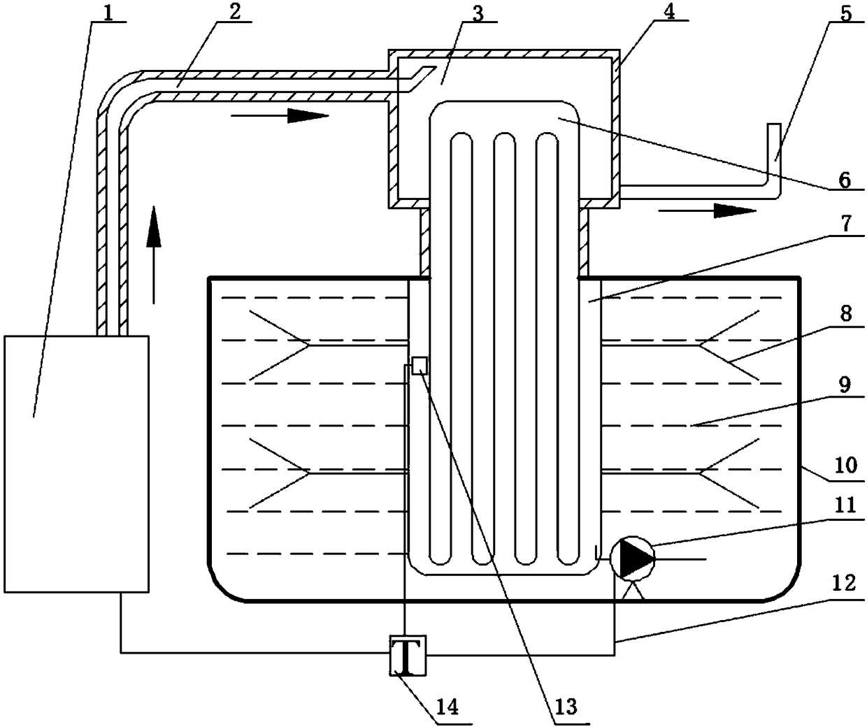
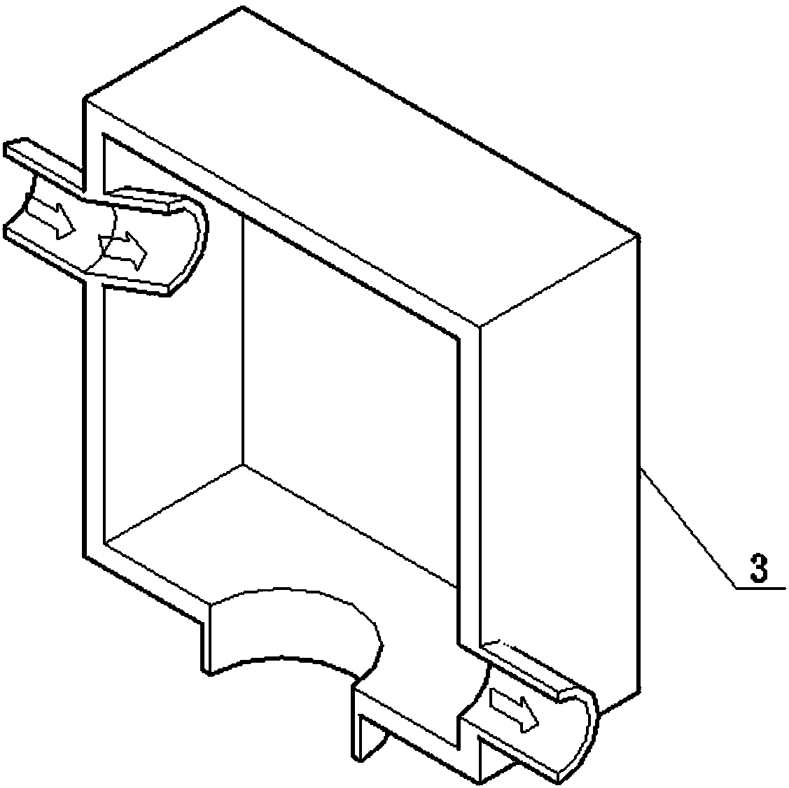
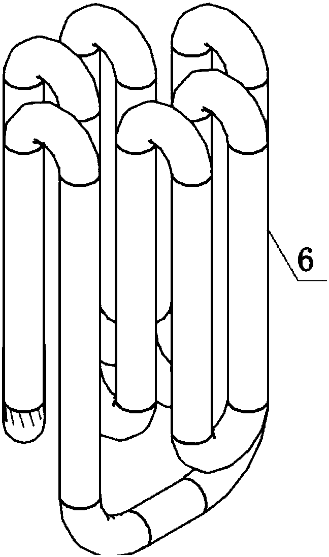
[0030] figure 1 The structure diagram of the temperature control device of the oil storage system of the generator set of the polar scientific research station of the present invention is given. The exhaust end of the cylinder of the generator set 1 is connected to the first end of the smoke inlet pipe 2, the outer periphery of the smoke inlet pipe 2 is wrapped with insulation material 4, and the end of the smoke inlet pipe 2 is connected to the smoke inlet end of the heat storage smoke chamber 3, The flue gas outlet end of the hot smoke chamber 3 is connected to the smoke exhaust pipe 5 leading to the external environment, the evaporation section of the self-circulating heat exchange tube 6 is embedded in the heat storage smoke chamber 3, and the condensing section is placed in the sleeve 7. The heat exchange ribs 8 are connected to the periphery. The sleeve 7 and heat exchange ribs 8 are ...


PUM


Abstract

The invention discloses a temperature control device of an oil storage system of a generator set of a polar scientific research station. The temperature control device comprises the generator set and the oil storage system; the generator set comprises an oil inlet and a smoke outlet; and a sleeve is arranged inside the oil storage system, heat exchange rib plates are arranged on the outer wall of the sleeve, a self-circulation heat exchange pipe embedded into the sleeve and attached to a cavity of the sleeve is arranged inside the sleeve, the lower end of the self-circulation heat exchange pipe is located in the oil storage system, the upper end of the self-circulation heat exchange pipe is located in a thermal storage smoke chamber, the self-circulation heat exchange pipe comprises a plurality of vertical pipes and elbows located at the ends of the vertical pipes, the plurality of vertical pipes are connected to form a closed pipe, and the self-circulation heat exchange pipe is filled with phase change working media distributed in the vertical pipes. According to the temperature control device, heat transfer is realized, the heat in smoke discharged by the generator set of the polar scientific research station can be efficiently recycled and can be used for realizing temperature control of the oil storage system of the generator set, and therefore the economical efficiency and the reliability of operation of the generator set are greatly improved in high-altitude and low-temperature environment.

Description

Technical field [0001] The invention relates to a heat storage and temperature control device, in particular to a temperature control device for an oil storage system of a generator set in a polar scientific research station by using the waste heat of the exhaust gas of a diesel generator set in a polar low temperature environment. Background technique [0002] The energy support of the Polar Science Research Station mainly comes from the power generation of the generator set. The low temperature characteristics of the polar region will cause the fluidity of the diesel to decrease, which will lead to the problem of poor fuel supply or even flameout of the diesel generator set. Therefore, effective preheating and uniform temperature of the oil storage in the polar scientific research station is an important measure to ensure the efficient and smooth operation of the generator set in a low temperature and low pressure environment. At present, there are three main methods for prehea...

Claims


Application Information

Patent Timeline
Patent Type & Authority Patents(China)
IPC IPC(8): F02M31/16F01N5/02
CPCF01N5/02F02M31/16Y02T10/12
Inventor 陈永平赵阳高崴
Owner SOUTHEAST UNIV
Why Eureka
Try Eureka