A liquid hydrogen subcooling acquisition device

An acquisition device and supercooling degree technology, which is applied in the field of liquid hydrogen supercooling degree acquisition device, can solve problems such as low liquid supercooling degree, liquid solidification, low-temperature propellant leakage, etc., and achieve reduced boiling degree and reduced supercooling time , the evenly distributed effect of

Active Publication Date: 2018-11-09
XI AN JIAOTONG UNIV
View PDF5 Cites 0 Cited by
  • Summary
  • Abstract
  • Description
  • Claims
  • Application Information

AI Technical Summary

Problems solved by technology

At present, most of the thermodynamic states of low-temperature propellants are near the boiling point, and their thermophysical properties are obviously insufficient, especially for liquid hydrogen. The outstanding disadvantages are: low density and sensible cooling capacity per unit volume
When the pumping speed of the vacuum pump is increased, it will bring two fatal consequences to the system: ① It will cause the storage tank to vibrate violently. Due to the increase of the pumping speed, the pressure of the air pillow in the storage tank will decrease rapidly, and the gas-liquid interface in the storage tank will occur. Violent boiling, like water boiling in an electric kettle, causes strong vibrations in large storage tanks, which can cause loose screws and parts to fall, or cause resonance, weld cracks, and low-temperature propellant leakage; ② cause low-temperature propellant The temperature is seriously stratified, especially near the triple point. Due to the fast pumping speed, the liquid at the gas-liquid interface in the storage tank will freeze, and the liquid at the bottom is actually not supercooled.

Method used


Image

  • A liquid hydrogen subcooling acquisition device

Examples


Embodiment Construction

[0018] The present invention will be further described below in conjunction with accompanying drawing.

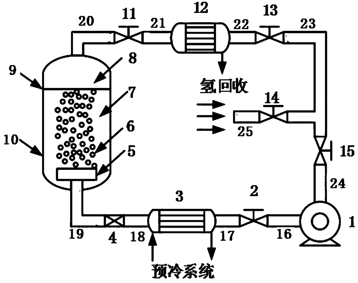
[0019] refer to figure 1 , a liquid hydrogen subcooling acquisition device, including a compressor 1, the outlet of the compressor 1 is connected to the inlet of the first valve 2 through the first pipeline 16, and the outlet of the first valve 2 is connected to the pre- The inlet of the precooling heat exchanger 3 in the cold system is connected, the outlet of the precooling heat exchanger 3 is connected with the inlet of the throttling device 4 through the third pipeline 18, and the outlet of the throttling device 4 is connected through the fourth pipeline 19 and the bubbling The inlet of the device 5 is connected, the bubbling device 5 is located in the liquid hydrogen 7 of the subcooler 10, and the bubbling device 5 forms helium bubbles 6 in the liquid hydrogen 7;

[0020] The outlet of the gas hydrogen 8 of the subcooler 10 is connected with the inlet of the second va...


PUM


Abstract

A liquid hydrogen subcooling acquisition device, comprising a compressor, the outlet of the compressor is connected to the inlet of the precooling heat exchanger connected in the precooling system, the outlet of the precooling heat exchanger is connected to the inlet of the throttling device, The outlet of the throttling device is connected to the inlet of the bubbling device. The bubbling device is located in the liquid hydrogen of the subcooler. The gas hydrogen outlet of the subcooler is connected to the inlet of the separation device. The hydrogen gas outlet of the separation device is used for hydrogen recovery. The separation device The outlet of the helium gas is connected with the outlet of the fourth valve and the inlet of the fifth valve, the inlet of the fourth valve communicates with helium, and the outlet of the fifth valve is connected with the inlet of the compressor. The present invention combines bubbling refrigeration and adiabatic throttling The refrigeration process is combined together, and the hydrogen recovery system is considered, so that the cost of obtaining the subcooling degree of liquid hydrogen is greatly reduced, the supercooling time is reduced, the boiling degree of the main liquid hydrogen is weakened, the vibration of the subcooler is reduced, and the temperature field of the liquid hydrogen is reduced. more evenly distributed.

Description

technical field [0001] The invention relates to the technical field of low-temperature propellant supercooling, in particular to a liquid hydrogen supercooling acquisition device. Background technique [0002] Cryogenic propellants (such as liquid hydrogen, liquid oxygen, liquid methane, etc.) have become the most widely used group of propellants for large launch vehicles due to their advantages of non-toxicity, pollution-free, low cost, high specific impulse, and high thrust. The specific impulse is 30% to 40% higher than that of normal temperature propellants. At present, most of the thermodynamic states of low-temperature propellants are around the boiling point, and their thermophysical properties are obviously insufficient, especially for liquid hydrogen. The outstanding disadvantages are: low density and sensible cooling per unit volume. In order to improve the thermodynamic performance of the low-temperature propellant, supercooling is used to improve the deficiency ...

Claims


Application Information

Patent Timeline
Patent Type & Authority Patents(China)
IPC IPC(8): F25B1/00
CPCF25B1/005F25B2500/05
Inventor 厉彦忠谢福寿王鑫宝王磊马原
Owner XI AN JIAOTONG UNIV
Why Eureka
Try Eureka