Eureka AIR delivers breakthrough ideas for toughest innovation challenges, trusted by R&D personnel around the world.

Ballistic wave-based automatic target scoring device, measurement method and data processing algorithm

A ballistic wave and automatic technology, applied in the direction of targets, target indication systems, offensive equipment, etc., can solve the problems of inability to obtain bullet trajectory information, large increase in target frame weight and volume, high processing costs of target frames, and reduce weight and volume , Simplified target surface structure, simple layout and construction

Inactive Publication Date: 2016-12-21
唐玉志 +1
View PDF5 Cites 2 Cited by
  • Summary
  • Abstract
  • Description
  • Claims
  • Application Information

AI Technical Summary

Problems solved by technology

[0004] The above-mentioned acoustic automatic target reporting system has the following disadvantages: to prevent bullets from hitting the acoustic sensor, bulletproof steel plates need to be installed on the target frame, and the processing cost of the target frame is high and difficult; the weight and volume of the target frame with additional sensors and bulletproof steel plates Large increase, the drive motor with a larger torque is required in the lifting and falling target, and a larger power supply capacity is required when used in the field; after the bulletproof steel plate is hit by bullets many times, it still needs to be replaced, and the maintenance cost is high in the later period; the system can only obtain The bullet hits the target point, and the bullet trajectory information cannot be obtained

Method used


Image

  • Ballistic wave-based automatic target scoring device, measurement method and data processing algorithm
  • Ballistic wave-based automatic target scoring device, measurement method and data processing algorithm
  • Ballistic wave-based automatic target scoring device, measurement method and data processing algorithm

Examples


Embodiment Construction

[0045] The present invention will be described in detail below in conjunction with the accompanying drawings.

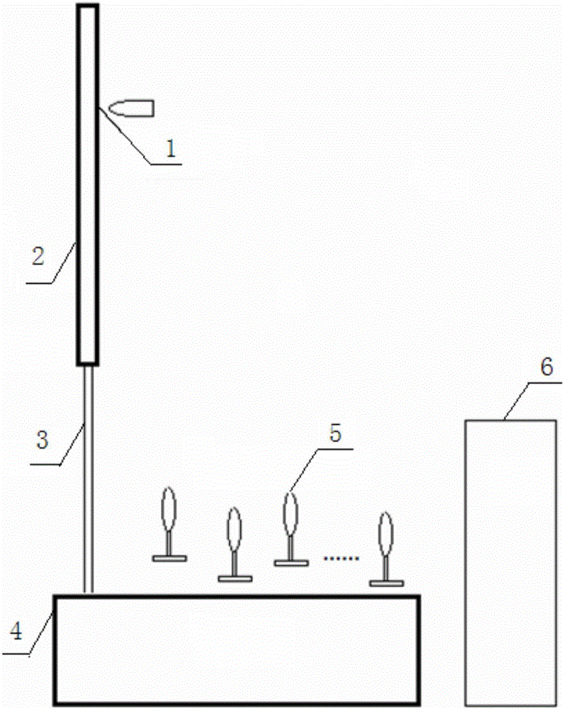
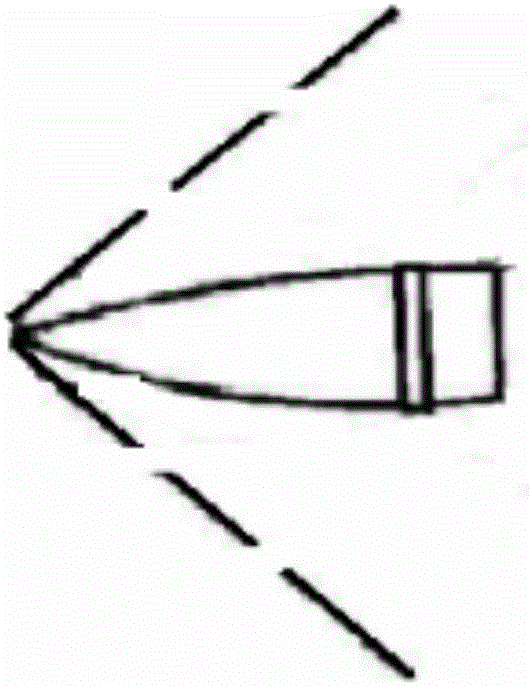
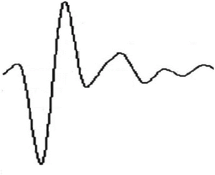
[0046] see Figure 1 to Figure 5 ,in figure 1 It is a structural schematic diagram of the acoustic signal detection device of the ballistic wave-based automatic target reporting device proposed by the present invention; figure 2 It is a schematic diagram of bullet radiation cone wave in the present invention; image 3 It is a schematic diagram of the "N" wave received by the acoustic sensor proposed by the present invention; Figure 4 It is a data transmission structure diagram of the ballistic wave-based target reporting device proposed by the present invention; Figure 5 It is a schematic diagram of equipment connection of the ballistic wave-based target reporting device proposed by the present invention.

[0047] Such as Figure 1 to Figure 5As shown, an automatic target reporting device based on ballistic waves is characterized in that it includes an acoust...


PUM


Abstract

The invention discloses a ballistic wave-based automatic target scoring device. The device comprises an acoustic signal detection device, a background processing device, a display control terminal and a wireless communication module used for performing data communication between the background processing device and the display control terminal, the acoustic signal detection device consists of a base, a supporting structure arranged on the base, a target frame connected with the supporting structure, and a mask body arranged in front of the base, a plurality of acoustic sensors are fixedly arranged on the base, output ends of the acoustic sensors are connected with an acsoutic regulating instrument for acquiring, regulating and converting acoustic signals into digital signals, the background processing device comprises an acoustic regulating instrument for acquiring the acoustic sensors and converting into digital signals, and a signal processing unit for preprocessing the acoustic signals, and the display control terminal comprises a display device and a central data statistics and management module. According to the device, the sensors are simply distributed and constructed, and the later-period maintenance work can be greatly reduced.

Description

technical field [0001] The invention relates to an acoustic measurement system, in particular to an automatic target reporting device based on ballistic waves, a measurement method and a data processing algorithm. Background technique [0002] Shooting training is a routine training in the military, public security, armed police and other systems. The statistics of the hit situation during shooting usually rely on manual reading of the number of rings on the target paper. After the 1990s, an automatic target reporting system that used acoustic sensors to measure the number of hit rings appeared. [0003] The principle of the original acoustic automatic target reporting system is that eight acoustic sensors are arranged on the four sides of the target frame. , the time of the acoustic signal received by each sensor is inconsistent, and the time difference between the arrival of the acoustic signal to each sensor is used to determine the position of the hit point according to...

Claims


Application Information

Patent Timeline
Patent Type & Authority Applications(China)
IPC IPC(8): F41J5/06
CPCF41J5/06
Inventor 唐玉志鲁亚鹏李剑平李阳
Owner 唐玉志
Why Eureka
Eureka Blog
Learn More