Visible light combined positioning system and method based on particle filter

A combined positioning and particle filtering technology, which is applied in the beacon system, radio wave measurement system, positioning and other directions using electromagnetic waves, and can solve the problems of multi-path interference areas where the visible light signal is not covered, and the positioning cannot be carried out.

Inactive Publication Date: 2016-12-21
BEIJING INSTITUTE OF TECHNOLOGYGY
View PDF6 Cites 15 Cited by
  • Summary
  • Abstract
  • Description
  • Claims
  • Application Information

AI Technical Summary

Problems solved by technology

[0009] The present invention aims to solve the defect that the existing combined positioning system of visible light positioning and inertial navigation cannot perform positioning

Method used


Image

  • Visible light combined positioning system and method based on particle filter
  • Visible light combined positioning system and method based on particle filter
  • Visible light combined positioning system and method based on particle filter

Examples


Embodiment 1

[0059] This embodiment describes the process of applying the "system and method for combining visible light positioning and inertial positioning based on particle filter" of the present invention to the scene of positioning and recognition targeting pedestrians.

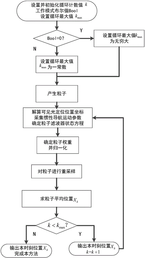
[0060] figure 1 It is an algorithm flow chart of this method and a flow chart of this embodiment. As can be seen from the figure, the method includes the following steps:

[0061] Step A: Set and initialize the loop count value k, the working mode Boolean value Bool; set the loop maximum value k max ;

[0062] Specifically in this embodiment, k is initialized to 1;

[0063] Step B: Determine whether the Bool value is 0, and perform corresponding operations:

[0064] B.1 If yes, corresponding figure 1 "Bool=0?" in the Y output, set the loop maximum k max is infinity;

[0065] B.2 If not, corresponding figure 1 "Bool=0?" in the output of N, loop maximum k max is a constant;

[0066] Specific to this embodimen...

Embodiment 2

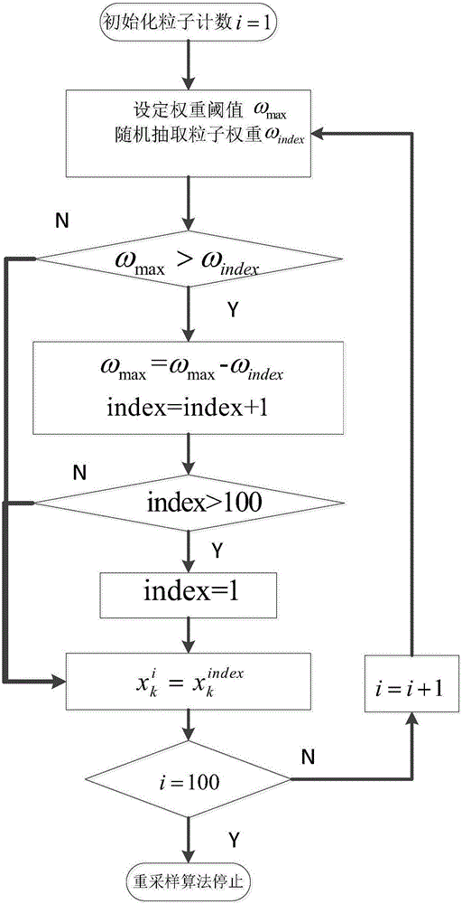
[0082] This embodiment specifically illustrates the simple random resampling method described in step 5 of the present invention and the resampling algorithm of step F in embodiment 1, and the algorithm flow is as follows figure 2 shown. From figure 2 It can be seen that the specific steps of the resampling algorithm are:

[0083] Step F.1: Initialize particle count i=1;

[0084] Step F.2: Set weight threshold ω max and random particle weight ω index ;

[0085] where the weight threshold is ω max =2×max(ω)×rand, rand is a random number uniformly distributed between 0 and 1, and max(ω) is the maximum weight among all 100 particles at time k;

[0086] Among them: random selection of particle weight ω index The method is to randomly extract the index particle from the i-th to the 100th particle, and record the weight of the particle as ω index ;

[0087] Step F.3: Determine whether ω max > ω index , and perform corresponding operations, specifically:

[0088] F.31: ...

Embodiment 3

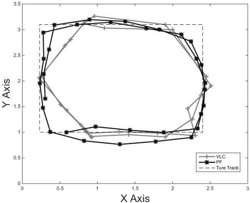
[0099] In this embodiment, according to the parameters described in Embodiment 1 and the resampling method described in Embodiment 2, the k obtained from steps 1 to 7 of the present invention are specifically described. max A combined positioning position result is compared with the positioning position result obtained by the existing visible light positioning method at the same time. The comparison results are as follows: image 3 .

[0100] image 3 Among them, X Axis represents the abscissa, and its unit is meter; Y Axis represents the vertical coordinate, and its unit is meter; image 3 The dotted line in the middle, that is: "True Track" is the real trajectory of pedestrians; the dashed line in the star, that is: "PF" is the step 1 of "a particle filter-based combined visible light positioning method (referred to as this method)" proposed by the present invention The combined positioning position trajectory calculation result obtained in step 7; the crossed line, that i...


PUM


Abstract

A visible light combined positioning system and method based on particle filter are disclosed, the visible light combined positioning method based on the particle filter (the method for short) and the system supporting the method are disclosed, and the visible light combined positioning method based on the particle filter is as follows: 1 initializing a cycle count value by a system initialization unit, setting a working mode Boolean value and a maximum cycle count value, and setting an initial coordinate value of a combined positioning position at the moment of K = 1; 2 producing particles; 3 resolving visible light positioning position coordinates, gathering inertial navigation motion parameters and determining a particle filter state equation; 4 calculating particle weight and normalizing; 5 resampling the particles to obtain a new particle swarm; 6 calculating combined positioning position coordinates; and 7 judging whether the cycle count value reaches the maximum count value, and performing corresponding operation. The system and the method greatly reduce errors caused by visible light positioning system signal shaking, map limitation and signal blockage, greatly overcomethe problem of pure inertial navigation system cumulative errors increasing with time, and have a wide application prospect.

Description

technical field [0001] The invention relates to a particle filter-based visible light combined positioning system and method, and belongs to the technical fields of indoor positioning and visible light positioning. Background technique [0002] With the rapid development of smart device technology, people's demand for location-based services is increasing. However, because traditional positioning technologies such as GPS cannot meet the needs of indoor fine positioning, indoor positioning technologies represented by Bluetooth, WiFi, and visible light positioning technologies have begun to emerge. Among them, visible light positioning is favored for its high precision, low cost, and easy implementation. However, visible light positioning technology is susceptible to problems such as multipath reflections, map limitations, and signal occlusion, thus limiting its practicality. [0003] Inertial navigation uses the carrier acceleration and angular velocity values ​​(may also i...

Claims


Application Information

Patent Timeline
IPC IPC(8): G01C21/16G01S1/70G01S5/16
CPCG01C21/165G01S1/70G01S5/16
Inventor 冯立辉李志天杨爱英吕慧超
Owner BEIJING INSTITUTE OF TECHNOLOGYGY
Why Eureka
Try Eureka