
Pressurizing device for detecting waterproof sealing performance of sensor

A detection sensor, waterproof sealing technology, applied in the direction of using liquid/vacuum for liquid tightness measurement, etc., can solve the problem of effective waterproof sealing performance of the sensor, and achieve the effect of solving the problem of waterproof detection, avoiding water ingress, and ensuring reliability.

Inactive Publication Date: 2016-12-21
NUCLEAR POWER INSTITUTE OF CHINA
View PDF10 Cites 2 Cited by
  • Summary
  • Abstract
  • Description
  • Claims
  • Application Information

AI Technical Summary

Problems solved by technology

Now also lack a kind of pressure boosting device that can solve whether the waterproof and sealing performance of the sensor during the test is effective, and can withstand the pressure level of the test to detect the waterproof and sealing performance of the underwater vibration measurement sensor

Method used


Image

  • Pressurizing device for detecting waterproof sealing performance of sensor
  • Pressurizing device for detecting waterproof sealing performance of sensor
  • Pressurizing device for detecting waterproof sealing performance of sensor

Examples


Embodiment 1

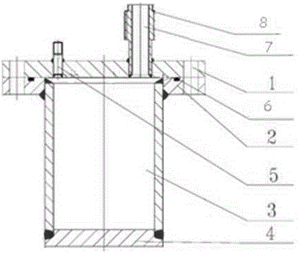
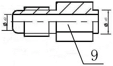
[0023] The present invention includes a supercharging device body used for measuring the waterproof sealing performance of the sensor. The sealing cover 1 of the supercharging device body is provided with an integrally formed supercharging nozzle 5 and a sensor wire outlet nozzle 7. The supercharging nozzle is connected to the external The pressure device is connected, the top of the sensor wire outlet nozzle 7 is connected to the sealing joint 9 through the sealing nut 11, and the through hole Фd212 for leading out the sensor wire is set inside the sealing joint 9, after the sensor wire is led out to the through hole Фd212, Fill the inner through hole Фd212 of the sealing joint 9 with waterproof and pressure-resistant glue, and let it fully cure.

[0024] when used in figure 1 Fill the device with water, put the sensor into the barrel of the supercharging device, the barrel is a stainless steel barrel structure, do a good job of sealing the sensor wire and the wire outlet noz...

Embodiment 2

[0027] This embodiment is preferably as follows on the basis of Embodiment 1: the supercharging device body includes a sealing cover 1, a cylinder flange 2, a cylinder 3 and a bottom plate 4, the bottom of the cylinder 3 is welded to connect the bottom plate 4, and the bottom of the cylinder 3 The top of the cylinder is welded to the flange 2 of the cylinder, the sealing cover 1 is located on the top of the flange 2 of the cylinder, and the flange 2 of the cylinder and the sealing cover 1 are connected by bolts. The barrel and the bottom plate of the supercharger body, and the barrel and the barrel flange are all connected by welding, and the barrel flange and the sealing cover are connected by bolts, using welding or bolts, so that The supercharging device itself has good stability, can withstand higher pressure, and will not leak.

Embodiment 3

[0029] This embodiment is preferably as follows on the basis of the above embodiments: an O-shaped rubber sealing ring groove 6 is also provided on the cylinder flange 2, and an O-shaped rubber sealing ring is installed in the O-shaped rubber sealing ring groove 6 for sealing. Since the cylinder flange and the sealing cover are connected by bolts, in order to prevent water leakage from the gap between the cylinder flange and the sealing cover, an O-shaped rubber sealing ring groove and an O-shaped rubber sealing ring are set up. Sealing treatment prevents water leakage and further improves the accuracy of the device inspection.


PUM


Abstract

The invention discloses a pressurizing device for detecting the waterproof sealing performance of a sensor. The pressurizing device comprises a pressurizing device body used for measuring the waterproof sealing performance of the sensor; the sealing cover of the pressurizing device body is provided with an integrally-formed pressurizing connection mouthpiece and a sensor wire outlet mouthpiece; the top of the sensor wire outlet mouthpiece is provided with a sealing joint through a sealing nut; a through hole phid2 into which a sensor wire can be led is formed in the sealing joint; after the sensor wire is led into the through hole phid2, the through hole phid2 in the sealing joint is filled with a waterproof pressure resisting adhesive; and the waterproof pressure resisting adhesive is fully cured. With the pressurizing device of the above structure adopted, the reliability of the waterproof sealing performance of the sensor before a test can be ensured, the sensor joint can be protected, and damage to the cable joint part of the sensor caused by water infiltration into the cable joint part can be avoided.

Description

technical field [0001] The invention relates to the field of supercharging detection, in particular to a supercharging device for testing the waterproof sealing performance of a sensor. Background technique [0002] In the flow-induced vibration test of nuclear reactor internals, the measured structures are all underwater, and the working environment of the measurement sensors used is mostly in water. Structural vibration is caused by the excitation of fluid flow, and due to the complexity of the measurement structure, the interaction between structures is difficult to calculate accurately in theory. Only by testing and using appropriate sensors to measure the vibration response of the structure can the flow-induced flow of the structure be obtained. Vibration response, so as to evaluate the flow-induced vibration behavior of the structure, to ensure the safety of the structure during the operation of the reactor. During the test, the flow of the fluid excites the structure...

Claims


Application Information

Patent Timeline
IPC IPC(8): G01M3/02
CPCG01M3/02
Inventor 许静丛滨杨杰马建中喻丹萍
Owner NUCLEAR POWER INSTITUTE OF CHINA
Features
  • Generate Ideas
  • Intellectual Property
  • Life Sciences
  • Materials
  • Tech Scout
  • Unparalleled Data Quality
  • Higher Quality Content
  • 60% Fewer Hallucinations
Learn More